EN
EN


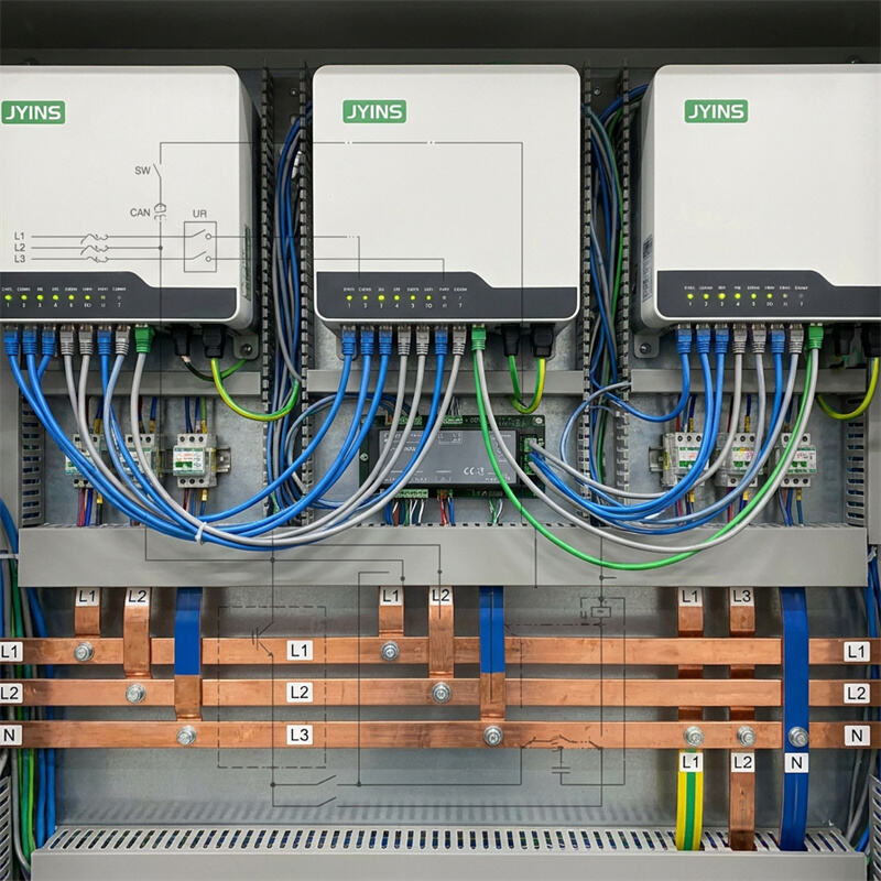
Introduction to Three-Phase Inverter Architectures
In heavy industrial workshops, commercial facilities, and remote mining sites, three-phase electrical power (380V, 400V, or 480V) is the standard for operating large electric motors, CNC machines, and heavy HVAC systems. When grid power is unavailable or unreliable, systems integrators often design off-grid power stations using multiple single-phase inverters wired together to generate a coordinated three-phase AC output.
While this modular approach offers redundancy and scalability, it introduces significant control complexities, particularly when the electrical loads on each of the three phases are unequal (unbalanced phase loads). Under these conditions, real-time communication between the inverters is not just a feature; it is a fundamental requirement for system stability.
This article examines why parallel communication mapping is critical for managing unbalanced phase loads in three-phase inverter systems.
Question: Why is parallel communication mapping critical when dealing with unbalanced phase loads in 3-phase inverter systems?
Parallel communication mapping is critical because it enables separate inverters to continuously synchronize their voltage phase angles at a precise 120-degree separation, dynamically adjust individual phase voltage outputs, and manage massive neutral currents. Without this high-speed, real-time data link (typically run over a CAN bus), unbalanced phase loads will cause voltage collapses on heavily loaded phases, over-voltage spikes on lightly loaded phases, phase-angle drift, and immediate system shutdown due to phase synchronization faults. High-quality systems utilize JYINS' fast parallel communication protocols to ensure dynamic phase-by-phase compensation.
The Physics of Three-Phase Systems and Parallel Inverters
A three-phase electrical system consists of three distinct live AC conductors (Phase A, Phase B, and Phase C) and a single shared Neutral conductor. For the system to operate correctly, the AC voltage sine wave of each phase must be shifted by exactly 120 electrical degrees relative to the other two phases. This precise angular displacement is what generates the rotating magnetic field required to drive industrial machinery.
When three separate single-phase inverters are connected to form a three-phase system, they must not operate independently. They must communicate continuously to coordinate their phase angles.
One inverter is designated as the 'Master' (Phase A), while the other two act as 'Slaves' (Phase B and Phase C). The Master inverter generates the fundamental reference clock. The Slave inverters monitor this clock and delay their own AC output generation by exactly 6.67 milliseconds (for 50 Hz systems) and 13.33 milliseconds respectively, maintaining the perfect 120-degree separation.
The Threat of Unbalanced Phase Loads
In a perfect B2B scenario, the electrical loads connected to Phase A, Phase B, and Phase C are identical. However, in real-world workshops and offices, balanced loading is rare. Single-phase loads (such as office lighting, computer workstations, and hand tools) are connected to individual phases relative to neutral. If Phase A is powering a heavy 5 kW single-phase welder, Phase B is powering a 1 kW air compressor, and Phase C has zero active load, the system is highly unbalanced.
In a standard, uncoordinated system, this imbalance causes severe electrical anomalies:
- Voltage Sag on the Heavy Phase: The inverter on Phase A experiences a sudden, massive current demand. Due to internal impedance, its output voltage will sag (e.g., dropping from 230V to 195V).
- Voltage Swell on the Light Phase: As Phase A sags, the neutral point of the system shifts. This electrical phenomenon, known as neutral point displacement, can cause the voltage on the unloaded Phase C to swell dangerously (e.g., rising from 230V to 265V), potentially destroying sensitive electronics connected to that phase.
- Phase-Angle Distortion: Heavy loading on a single phase introduces inductive lag. This lag shifts the phase angle, causing the 120-degree separation between phases to distort (e.g., shifting Phase A to 115 degrees). This distortion disrupts three-phase motors, causing them to draw excessive current, run hot, and lose torque.
- Neutral Wire Current Overload: In a balanced three-phase system, the return currents of all three phases cancel each other out, resulting in zero current in the neutral wire. However, under unbalanced conditions, the vector sum of the currents does not equal zero. The entire unbalance current must flow through the neutral wire, risking overheating and electrical fire if not monitored.
The Critical Role of Parallel Communication Mapping
To prevent voltage fluctuations and system shutdowns, high-speed parallel communication (using CAN bus or high-speed RS485 protocols) must be established between the inverters. This communication mapping works as a real-time feedback loop operating at millisecond intervals:
- Real-Time Voltage Compensation: The Master inverter continuously polls the voltage and current vectors of the Slave inverters. If Phase A reports a voltage sag, the Master instructs Phase A's inverter to slightly increase its internal boost ratio to compensate, while simultaneously adjusting the duty cycle of the other phases to keep the neutral point centered. This keeps all three phase voltages within a tight 2% tolerance.
- Phase-Locked Loop (PLL) Phase Stabilization: The communication link maps the active phase-locked loop (PLL) reference across all three units. If Phase A's phase angle shifts due to inductive load, the communication mapping allows Phases B and C to immediately adjust their output angles in real-time, maintaining the precise 120-degree relationship relative to the shifted reference. This prevents phase-angle drift faults.
- Shared Over-Current Protection: If the load on Phase A exceeds its individual capacity but the overall system capacity is healthy, the inverters can coordinate to trigger warnings or execute a controlled, synchronized shutdown. This is far better than a single phase suddenly tripping, which would instantly drop the remaining phases and damage connected three-phase motors due to single-phasing (running a three-phase motor on only two phases).
Implementation Guidelines for Systems Integrators
When installing a modular 3-phase inverter system using JYINS hardware, engineers must adhere to the following setup rules:
- Use Shielded Communication Cables: High-voltage AC lines generate electromagnetic interference. Always use high-quality, double-shielded RJ45 or CAN cables to connect the parallel communication ports of the inverters. Keep these communication lines physically separated from high-voltage AC and DC power cables.
- Install Terminator Resistors: In high-speed CAN bus networks, signal reflections can corrupt data. Ensure the physical termination DIP switches are set correctly (usually enabling a 120-ohm resistor on the first and last inverter in the communication chain).
- Program Correct Inverter Phase IDs: Each inverter must be explicitly programmed via its digital control interface to its designated phase (Phase A, B, or C) and parallel position. Double-phase mapping (e.g., accidentally setting two inverters to Phase B) will result in immediate system locking and synchronization error alarms.
Conclusion
Modular three-phase inverter installations provide outstanding power flexibility for B2B industrial systems, but they demand precise control. Unbalanced phase loads represent a serious threat to system stability, causing voltage sags, destructive voltage swells, and phase-angle distortion. Utilizing high-speed parallel communication mapping, such as the advanced CAN-bus synchronization systems engineered into JYINS inverters, allows individual units to act as a single, cohesive, intelligent system. This real-time coordination stabilizes voltages, protects equipment, and ensures reliable, continuous operations in the most demanding three-phase industrial workshops.
Table of Contents
- Introduction to Three-Phase Inverter Architectures
- Question: Why is parallel communication mapping critical when dealing with unbalanced phase loads in 3-phase inverter systems?
- The Physics of Three-Phase Systems and Parallel Inverters
- The Threat of Unbalanced Phase Loads
- The Critical Role of Parallel Communication Mapping
- Implementation Guidelines for Systems Integrators
- Conclusion