EN
EN


Introduction to DC Transmission Challenges
In remote B2B power applications, such as off-grid telecommunication towers, oil and gas monitoring stations, agricultural irrigation setups, and deep-well pumps, the physical layout of the electrical system is often constrained by geography. Frequently, the energy storage system (the battery bank) must be located a significant distance away from the power inverter or the active DC loads.
In these long-distance DC setups, systems integrators often face a frustrating troubleshooting hurdle: the inverter unexpectedly shuts down, reporting a 'Low Voltage Cutoff' (LVC) or 'Battery Under-Voltage' fault. This shutdown occurs even when the battery bank itself is fully charged and operating at a healthy voltage level. This phenomenon is known as nuisance tripping.
This article delivers a technical analysis of why LVC nuisance tripping occurs in long-distance DC transmission layouts and outlines specific engineering solutions to resolve it.
Question: Why does Low Voltage Cutoff (LVC) nuisance tripping occur in long-distance DC installations, and how can engineers resolve it?
LVC nuisance tripping occurs because long DC power cables have inherent electrical resistance. When high current is drawn during inverter startups or heavy loads, this resistance causes a significant voltage drop along the cable, according to Ohm's Law. Consequently, the voltage measured at the inverter's input terminals drops below the LVC threshold, even though the battery bank remains charged. To resolve this, engineers must calculate and minimize DC cable resistance, upgrade the system voltage, calibrate the inverter's LVC delay and threshold parameters, or utilize remote voltage sensing lines.
The Physics of DC Voltage Drop and Cable Resistance
Unlike AC transmission, where transformer stepping can easily mitigate voltage drops, DC transmission is highly sensitive to cable length and cross-sectional thickness. Every electrical conductor, even high-purity copper, has a specific resistance (rho).
According to Ohm's Law, the voltage drop (V_drop) across a pair of conductors is directly proportional to the current (I) flowing through the circuit and the total round-trip resistance (R) of the wire:
V_drop = I R
The resistance of the wire is determined by the formula:
R = rho ( 2 L ) / A
Where:
- rho is the resistivity of the material (for copper, rho is approximately 1.72 10^-8 ohm-meters).
- L is the one-way distance between the battery and the inverter.
- A is the cross-sectional area of the wire.
- The multiplier of 2 accounts for the round-trip distance (positive and negative conductors).
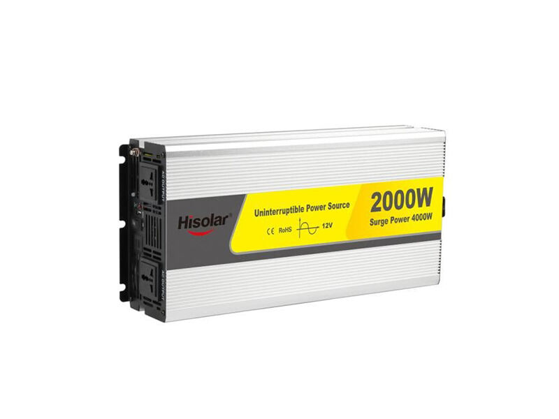
In a low-voltage DC system, current is incredibly high. For instance, a 12V 2 kW inverter drawing full load will pull approximately 166 Amperes of current. Under a heavy motor-startup surge, this current can spike to 400A or more.
If the inverter is located just 10 meters (33 feet) away from the battery bank, and is connected using standard 2 AWG (approx. 33.6 square mm) copper wire, the round-trip resistance of the 20-meter cable run is roughly 0.010 ohms.
When drawing 166A of continuous running current, the voltage drop is:
V_drop = 166A 0.010 ohms = 1.66V
If the battery bank is at a healthy 12.6V, the voltage arriving at the inverter's DC input terminals is only:
12.6V - 1.66V = 10.94V
This is close to the standard 10.5V LVC threshold. However, if a motor starts and the current surges to 350A, the voltage drop instantly spikes to:
V_drop_surge = 350A 0.010 ohms = 3.50V
The voltage at the inverter terminals drops to:
12.6V - 3.50V = 9.10V
Because 9.10V is far below the 10.5V LVC limit, the inverter's protection circuit immediately triggers an under-voltage cutoff, shutting down the AC output. The moment the inverter shuts down, the current draw drops to zero, the voltage drop disappears, and the inverter terminals jump back to 12.6V. To the technician, the battery bank appears full, and the shutdown seems like a hardware malfunction. This is the definition of LVC nuisance tripping.
Troubleshooting Step-by-Step Diagnostic Process
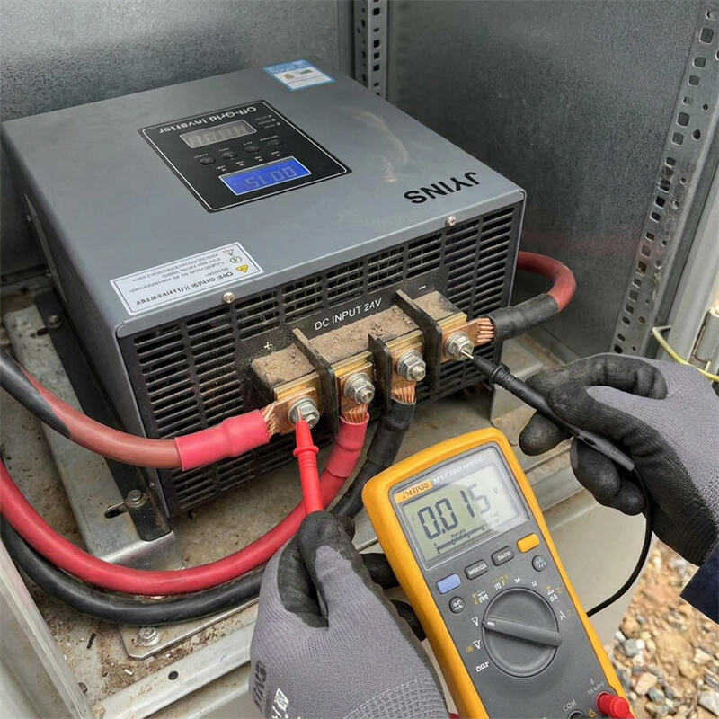
To diagnose and prove that LVC tripping is caused by cable resistance rather than a failing battery or inverter, follow this measurement procedure:
- Step 1: Measure Static Battery Voltage
Using a digital multimeter, measure the DC voltage directly across the battery bank terminals under no-load conditions. Note this value (e.g., 51.2V for a 48V system).
- Step 2: Measure Static Inverter Voltage
Measure the voltage directly at the inverter's DC input terminal blocks. Under no-load, the two readings should be identical.
- Step 3: Measure Voltage Under Active Load
Turn on the heaviest load in the system. While the load is running (or attempting to start), measure the voltage at the battery bank terminals and then immediately measure the voltage at the inverter's terminal blocks.
- Step 4: Analyze the Difference
If the battery bank voltage remains high (e.g., dropping from 51.2V to 49.8V) but the inverter terminal voltage sags significantly (e.g., dropping from 51.2V to 41.5V), you have confirmed a cable resistance issue. The difference (8.3V) is the voltage drop across the DC cabling.
Engineering Solutions to Eliminate LVC Nuisance Tripping
Once confirmed, systems integrators should deploy one or more of the following remediation techniques:
- 1. Increase System Nominal Voltage
The most effective way to reduce current (and thus voltage drop) is to design the system at a higher nominal DC voltage. Power (Watts) is the product of Voltage and Current (P = V I). If you increase the nominal voltage from 12V to 48V, the current required to deliver the same 2 kW load drops by 75% (from 166A down to only 41.5A). According to Ohm's Law, cutting the current by four reduces the voltage drop by 75%. Whenever possible, choose 48V DC architectures for long-distance runs.
- 2. Upsize the DC Conductor Gauge
If the system voltage cannot be changed, you must reduce the wire's resistance by increasing its cross-sectional area (A). Upgrade the cables to thick copper gauges such as 4/0 AWG (95 square mm) or run multiple parallel cables per pole. Ensure the conductors are high-quality, fine-stranded oxygen-free copper, which offers the lowest practical electrical resistance.
- 3. Adjust Inverter LVC Parameter Settings
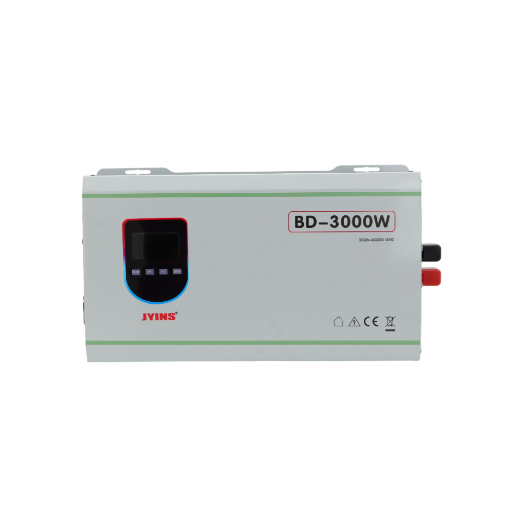
High-performance inverters, such as the JYINS programmable series, allow engineers to customize the LVC settings via the digital control software. Two parameters can be adjusted:
- Lower the LVC Threshold: You can slightly lower the cutoff voltage (e.g., from 10.5V to 10.0V) if your battery chemistry can safely handle the transient dip without damage.
- Add an LVC Delay Timer: Most JYINS units feature a programmable delay (e.g., 0 to 10 seconds). By setting a delay of 3 seconds, the inverter will ignore short under-voltage dips caused by motor-startup surges, allowing the motor to start and the voltage to recover before the protection circuit is triggered.
- 4. Implement Remote Voltage Sensing
Advanced industrial systems can utilize remote voltage sensing. A pair of thin, low-current wires are run directly from the battery terminals to the inverter's control board. The inverter uses these dedicated sensor wires to measure the true state of charge of the battery, bypassing the high-current power lines. The inverter will only execute an LVC shutdown if the true battery voltage drops, completely ignoring the cable voltage drop.
Conclusion
Low Voltage Cutoff (LVC) nuisance tripping in long-distance DC setups is a classic electrical engineering problem caused by cable resistance and high current demand. By applying Ohm's Law, systems integrators can calculate exact voltage drops and size copper conductors accordingly. Transitioning to higher nominal system voltages (such as 48V), upsizing cables to heavy-duty gauges, and utilizing JYINS' programmable LVC delays and remote sensing inputs will eliminate nuisance shutdowns. These steps ensure stable, continuous power delivery to critical off-grid infrastructure, regardless of physical site layout constraints.
Table of Contents
- Introduction to DC Transmission Challenges
- Question: Why does Low Voltage Cutoff (LVC) nuisance tripping occur in long-distance DC installations, and how can engineers resolve it?
- The Physics of DC Voltage Drop and Cable Resistance
- Troubleshooting Step-by-Step Diagnostic Process
- Engineering Solutions to Eliminate LVC Nuisance Tripping
- Conclusion