EN
EN


Q: Why do Railway and Rolling Stock applications require specialized vibration-resistant inverters?
Introduction: The Severe Physical Demands of Rail Environments
Railway transportation and rolling stock (passenger trains, high-speed rail, locomotives, and subways) are critical components of global infrastructure. These transport systems carry millions of passengers and billions of tons of freight every single day. To ensure a comfortable passenger experience and run vital electronic systems, train cars are equipped with high-tech onboard accessories. These include Wi-Fi routers, passenger charging outlets, LED displays, security cameras, HVAC controllers, and automated door mechanisms.
All of these onboard electronic devices must be supplied with stable, regulated AC electricity. Because trains draw power from high-voltage DC overhead lines, third rails, or heavy-duty battery banks, they rely on specialized onboard DC-AC power inverters to convert this raw DC energy into clean AC power.
In rail applications, the physical forces acting on these power inverters are incredibly severe. A train moving at 100 to 300 kilometers per hour experiences continuous, multi-axis physical stresses. Commercial or residential-grade inverters would quickly fail in this environment, often within a few weeks or months. Ensuring continuous operation requires the selection of specialized, highly engineered vibration-resistant railway-grade inverters.
This article details why railway and rolling stock environments are so damaging to standard power electronics, outlines the specific design features required for railway-grade inverters, and explores how JYINS Electrical high-reliability power solutions are engineered to withstand these extreme physical environments.
The Physics of Rail: Multi-Axis Vibration and Mechanical Shock
To understand why specialized inverters are mandatory for trains, we must analyze the physical forces they experience during normal transit:
- Continuous Low-Frequency Vibration: As a train's steel wheels roll over steel tracks, high-frequency micro-vibrations and low-frequency oscillations are constantly generated. These vibrations travel up through the wheels, bogies, and chassis of the train cars, directly impacting any onboard electrical cabinets. This vibration is multi-axis, meaning it acts simultaneously in the vertical, lateral, and longitudinal directions.
- Severe Mechanical Shock: Trains experience high-intensity mechanical shocks during specific operational events. These events include locomotive coupling, emergency heavy braking, negotiating tight curves, and traversing track switches or rail expansion joints. These shocks can reach high-G forces, creating immense localized physical stresses inside the electrical enclosures.
Key Engineering Failures in Non-Railway Inverters
If a standard, non-ruggedized inverter is installed on a train, these physical forces will trigger several classic engineering failure modes:
- Component Fatigue and Lead Cracking: Standard inverters contain heavy electronic components like large copper-wound transformers, filter inductors, and large electrolytic capacitors. Under continuous vibration, these heavy components act as cantilevers. Their heavy weight places immense mechanical strain on their copper leads and solder joints. Over time, this leads to metal fatigue, cracking of solder joints, and open-circuit failures.
- Fastener Backing-Out: Standard screw terminals, bolts, and physical fasteners rely on friction to stay tight. Continuous vibration acts as a microscopic lever, slowly loosening these screws. Once a terminal screw backs out, the electrical connection becomes loose. This leads to high contact resistance, localized heating, arcing, and eventual thermal damage or electrical fires.
- Internal Chafing and Short Circuits: Vibration causes internal wires, cables, and components to rub against each other or against the metal walls of the inverter's chassis. Over time, this constant rubbing chafes through the plastic insulation of the wires, leading to direct copper-to-metal short circuits and system failures.
Essential Design Requirements for Railway-Grade Inverters
To survive the harsh physical dynamics of rolling stock, railway-grade inverters must be engineered in compliance with strict international standards, incorporating several physical design features:
1. Absolute Compliance with EN 50155 / IEC 60571 Standards
The ultimate benchmark for any electronics deployed on railway rolling stock is the European Standard EN 50155 (or its international equivalent IEC 60571). This standard mandates that any electronic equipment must undergo rigorous testing to prove its resilience against:
- Mechanical Shock and Vibration: Testing includes subjecting the inverter to multi-axis vibration testing for hours, as well as high-G impact shock testing, matching the conditions experienced by passenger cars (Category 1, Class B classification).
- Extreme Temperature and Humidity: Operating temperatures must be supported from minus 25 to plus 70 degrees Celsius, including short-term exposure to plus 85 degrees Celsius.
- Input Voltage Fluctuations and Sags: Inverters must handle wide variations in DC input voltage without shutting down or degrading output quality.
JYINS railway-grade power solutions are fully designed to comply with these rigorous standards.
2. Spring-Loaded Tension Terminals (No Screw Terminals)
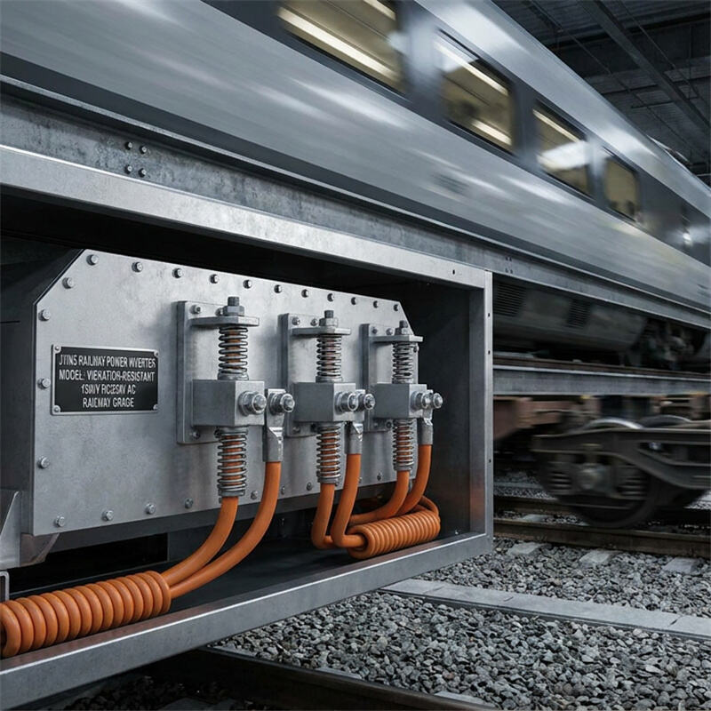
To completely eliminate the risk of loose connections caused by vibration, railway-grade inverters must utilize spring-loaded tension terminals (such as cage-clamp connectors) for all high-current wire connections. These connectors use a continuous mechanical spring to compress the wire against the copper busbar, ensuring that even under severe G-forces, the connection remains tight and secure, preventing arcing and voltage drops.
3. High-Mass Component Potting and Mechanical Anchoring
All heavy, high-mass components inside a JYINS railway inverter are physically secured to the chassis. Large copper transformers and inductors are completely encased or 'potted' in high-grade, thermally conductive epoxy compounds. This potting process distributes physical forces evenly across the chassis, preventing any strain on the component's electrical pins or solder connections.
4. Rugged Structural Enclosure with Lockable Fasteners
The inverter chassis must be constructed from thick, high-strength structural metal, and all assembly screws must be locked in place using nylon-locking nuts (Nyloc), high-strength thread-locking fluid (such as Loctite), or split-lock washers. This ensures that no part of the outer chassis or inner casing can come loose under years of high-speed travel.
Conclusion: Selecting Rail Uptime with JYINS Technology
In the railway industry, reliability and safety are the twin pillars of success. Equipment failure on a train can cause passenger complaints, delay schedules, and shut down critical communications and safety systems.
By specifying JYINS specialized, EN 50155 compliant vibration-resistant pure sine wave inverters, railway project managers and systems integration engineers build a bulletproof electrical infrastructure. JYINS inverters provide the mechanical potting, spring-loaded terminals, and rugged chassis designs needed to survive decades of continuous multi-axis rail vibration. Partner with JYINS to keep your rolling stock powered and moving safely forward.
Table of Contents
- Introduction: The Severe Physical Demands of Rail Environments
- The Physics of Rail: Multi-Axis Vibration and Mechanical Shock
- Key Engineering Failures in Non-Railway Inverters
- Essential Design Requirements for Railway-Grade Inverters
- 1. Absolute Compliance with EN 50155 / IEC 60571 Standards
- 2. Spring-Loaded Tension Terminals (No Screw Terminals)
- 3. High-Mass Component Potting and Mechanical Anchoring
- 4. Rugged Structural Enclosure with Lockable Fasteners
- Conclusion: Selecting Rail Uptime with JYINS Technology