EN
EN


Introduction to Isolation Resistance in Solar PV Arrays
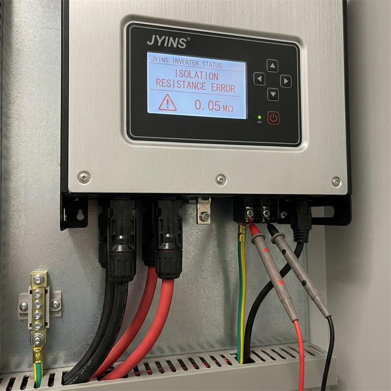
In high-voltage commercial and industrial solar installations, safety monitoring is paramount. Among the various self-diagnostic error codes a solar PV inverter can display, an 'Isolation Resistance Error' (often labeled as 'R_iso Error' or 'Insulation Fault') is one of the most critical. When this fault occurs, the inverter refuses to connect to the utility grid or start power conversion. It remains locked in a safety shutdown state until the underlying issue is resolved.
While this error can be frustrating for plant operators, it is a vital protective measure designed to prevent electrical fires and protect technicians from lethal shocks. This article explores the electrical principles behind isolation resistance, explains why the inverter triggers this fault, and provides a systematic diagnostic methodology to resolve it.
Question: Why do Inverters report 'Isolation Resistance' errors in solar arrays, and how to fix them?
An inverter reports an 'Isolation Resistance' error when it detects that the electrical insulation of the DC solar array has degraded, allowing a path for current to leak from the high-voltage DC conductors to the earth. To fix this error, engineers must understand how the inverter measures insulation, physically isolate and test individual PV strings using a specialized megohmmeter (Megger), trace the leakage path back to damaged cabling or moisture-ingress points, and execute proper physical repairs.
Understanding the Physics of Isolation Resistance
To understand this error, we must look at the circuit of a solar array. A solar photovoltaic array consists of multiple modules wired in series (strings) to produce high DC voltages, often ranging from 600V to 1500V DC. These strings are suspended on metal mounting racks, which are physically connected to the earth via grounding electrodes.
Under normal, safe operating conditions, the positive and negative conductors of the PV strings are fully insulated from the metal racks and the ground. The electrical resistance between the live DC conductors and the earth is extremely high, typically exceeding several tens of megaohms.
Before starting up each morning, the solar inverter performs an automatic self-test called the insulation resistance test (R_iso measurement). The inverter injects a low DC test voltage (usually 500V or 1000V DC) between its internal DC bus terminals and the AC grounding terminal (earth). It then measures the resulting leakage current flow.
Using Ohm's Law (Resistance = Voltage / Current), the inverter's microcontroller calculates the isolation resistance (R_iso). According to international safety standards (such as IEC 62109-2), if the calculated R_iso falls below a critical threshold (typically 100 kiloohms or 1 kiloohm per volt of array voltage), the inverter will flag an isolation fault and abort startup. This is because a low resistance means that high-voltage current is leaking to the ground, posing a severe threat.
The Hazards of Low Isolation Resistance
Ignoring a low isolation resistance warning is extremely dangerous for two primary reasons:
- Fire Hazard: High-voltage DC currents are highly prone to sustained electric arcing. If a live conductor has compromised insulation and touches a metallic, grounded PV rack, it can generate high-temperature electrical arcs. These arcs can easily ignite dry leaves, dust, or building materials, leading to catastrophic rooftop fires.
- Shock Hazard: In a healthy, fully isolated PV array, touching a single conductor is relatively safe because there is no return path. However, if there is an active ground fault in the array, the entire metallic mounting structure becomes electrically energized relative to the earth. A technician touching the mounting frame can complete the circuit to the ground, sustaining a lethal electric shock.
Common Causes of R_iso Errors
The degradation of DC insulation in a solar array is usually caused by environmental factors and mechanical wear over time. The most frequent causes include:
- Moisture Ingress: Water is highly conductive. If rain or condensation penetrates an MC4 connector, an array junction box, or a combiners panel, it forms a conductive bridge between the live terminals and the grounded enclosure. This is why R_iso errors often occur on rainy mornings and disappear once the sun dries out the array.
- Damaged Cable Insulation: DC cables can be chewed by rodents, abraded by sharp edges of metal mounting rails due to wind-induced movement, or degraded by prolonged UV exposure if non-UV-rated wiring was used. Compromised outer sheaths expose the bare copper conductor to the earth.
- Degradation of PV Module Backsheets: The backsheet of a solar panel provides the primary insulation between the silicon cells and the rear aluminum frame. Over years of thermal cycling, low-quality backsheets can crack, allow moisture penetration, and create a leakage path to the grounded module frame.
- Chemical Corrosion: In agricultural settings or chemical factories, ammonia or acidic airborne pollutants can degrade insulation materials, accelerating leakage pathways.
Step-by-Step Diagnostic and Resolution Procedure
To troubleshoot and resolve an insulation fault, B2B maintenance engineers and systems integrators should follow this safe, structured diagnostic routine:
- Step 1: Safety First
Before opening any enclosures, turn off the AC circuit breaker to disconnect the inverter from the grid. Then, switch off the DC isolators. High-voltage DC is lethal; always wear appropriate personal protective equipment (PPE), including insulated gloves and safety glasses.
- Step 2: Read Inverter Diagnostic Logs
Check the inverter's display or monitoring app to see if the isolation error specifies a particular string or input channel. This helps narrow down the search area.
- Step 3: Visual Inspection
Conduct a thorough visual check of the physical array. Look for cables resting directly on sharp metal rails, sagging wires, broken conduit, or signs of water accumulation inside PV junction boxes. Pay close attention to damaged MC4 connectors lying in standing water on flat roofs.
- Step 4: String Isolation and Inverter Testing
Disconnect all PV strings from the inverter's DC inputs. Re-enable the inverter's power. If the R_iso error disappears and the inverter displays a 'No PV Input' state, the inverter's internal electronics are healthy, and the fault lies entirely in the external DC wiring. If the error persists with no cables attached, the inverter's internal monitoring circuitry may be damaged and require service.
- Step 5: Megohmmeter (Megger) Testing
With the strings disconnected from the inverter, use a dedicated insulation resistance tester (Megger) to test each string individually. Connect the positive probe of the Megger to the PV string's positive lead, and the negative probe to the grounded rack. Apply a test voltage of 1000V DC. Repeat the test for the negative lead to ground. A healthy string should read well above 10 megaohms. If a string reads below 100 kiloohms, you have isolated the faulty circuit.
- Step 6: Locate the Exact Fault Point
To find the specific module or connector causing the leak within a faulty string, use the 'division method.' Split the string in half by disconnecting the MC4 connector in the middle. Test both halves with the Megger. The half with the low R_iso reading contains the fault. Repeat this process of halving the circuit until you isolate the single faulty PV module or cable section.
- Step 7: Repair and Prevention
Once identified, replace the damaged cable, replace the faulty MC4 connector with a high-quality weather-tight model, or replace the degraded PV module. Ensure all DC cables are securely tied up off the roof surface or mounting rails using UV-resistant cable clips or routed inside heavy-duty plastic conduits.
Conclusion
An Isolation Resistance Error is a critical safety alert that should never be ignored or bypassed. By understanding the electrical principles of PV insulation, using high-quality diagnostic tools like a Megger, and following a systematic elimination process, B2B systems integrators can quickly identify leakage paths. Investing in robust DC cabling, weather-proof connectors, and high-performance JYINS diagnostic-enabled inverters ensures long-term operational safety and maximizes the uptime of commercial solar installations.
Table of Contents
- Introduction to Isolation Resistance in Solar PV Arrays
- Question: Why do Inverters report 'Isolation Resistance' errors in solar arrays, and how to fix them?
- Understanding the Physics of Isolation Resistance
- The Hazards of Low Isolation Resistance
- Common Causes of R_iso Errors
- Step-by-Step Diagnostic and Resolution Procedure
- Conclusion