EN
EN


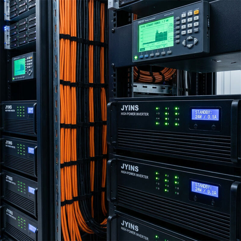
Introduction to Inverter Standby Losses
In large-scale commercial, industrial, and utility-scale battery energy storage systems (BESS), efficiency is calculated to the tenth of a percent. While a lot of attention is focused on the conversion efficiency of power inverters during peak production, a hidden financial drain often occurs when the system is inactive. This phenomenon is known as 'Ghost Power Consumption' or standby/idle loss.
When solar arrays go dark at night, or when industrial machinery is shut down during weekends, multi-kilowatt inverter banks remain connected to the system. Even when delivering zero AC power to the load, these units continue to draw current from the DC battery bank or the AC grid to keep their internal circuits energized. Over a year, this continuous, non-productive power draw can translate into thousands of kilowatt-hours of lost energy, directly impacting the system's return on investment (ROI).
This article analyzes the physics of standby losses in high-power inverters and outlines engineering strategies to eliminate ghost consumption.
Question: What causes 'Ghost Power Consumption' in large inverter arrays, and how can it be mitigated?
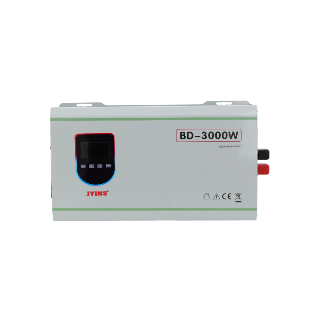
Ghost power consumption in standby mode is caused by active control electronics, cooling fan operations, and magnetic core losses in oversized transformers. To mitigate these standby losses in large-scale B2B systems, engineers must implement dynamic sleep-mode thresholds, configure intelligent master-slave parallel clustering, install external low-consumption DC isolation contactors, and select high-efficiency toroidal-based low-frequency or high-frequency inverters designed by JYINS with integrated low-power eco modes.
The Physics and Sources of Standby Consumption
To eliminate ghost power, we must first locate where this energy is being consumed within the inverter architecture. There are three primary hardware categories responsible for idle power draw:
- Active Control and Communication Electronics: Every industrial inverter contains an array of digital signal processors (DSPs), microcontrollers, Wi-Fi/GPRS telecommunication modems, and sensor arrays (monitoring voltage, current, and temperature). These control boards require a constant, stable DC voltage (usually 5V or 12V) supplied by an internal auxiliary power supply. This continuous power draw is constant regardless of whether the inverter is delivering 0% or 100% load.
- Gate Driver and Switching Losses: To produce an AC sine wave, the inverter's microcontroller continuously sends high-frequency pulse-width modulation (PWM) signals to the gates of the power MOSFETs or IGBTs. The physical switching of these semiconductors, even under zero load, consumes current due to the parasitic capacitance of the semiconductor gates. This is known as idle switching loss.
- Magnetic Core and Transformer Losses: Low-frequency inverters utilize heavy copper transformers to step up voltage and isolate circuits. Even with no load connected to the AC output, the primary winding of the transformer is excited by the inverter's switching circuit. This excitation creates alternating magnetic fluxes within the steel core, resulting in continuous eddy current and hysteresis losses, collectively known as 'iron losses' or excitation power draw. In a large 10 kW low-frequency inverter, iron losses can easily exceed 80W to 150W of continuous power draw.
- Cooling Fan Operation: High-power inverters utilize active fan cooling. If the inverter's temperature remains high after a high-load period, or if the fan control algorithms are poorly programmed, the cooling fans may continue running at full speed under zero load, drawing 20W to 100W per fan.
Quantifying the Financial Impact on B2B Systems
Let us consider a medium-sized off-grid industrial microgrid utilizing five 10 kW low-frequency parallel inverters for a total capacity of 50 kW.
If each inverter has an idle standby consumption of 120 Watts, the total standby draw of the array is 600 Watts.
Over a typical 14-hour non-productive period (from 5:00 PM to 7:00 AM the next morning), this array will consume:
0.6 kW 14 hours = 8.4 kWh of energy per day.
Over an entire year, this standby loss totals:
8.4 kWh 365 days = 3066 kWh of wasted energy.
If the system relies on battery storage where the cost of stored energy is valued at 0.15 USD per kWh (factoring in PV capital costs and battery lifecycle degradation), this standby loss costs the facility 460 USD annually per site. For telecommunication tower operators with 1000 remote sites, this is a yearly loss of nearly half a million dollars.
Technical Solutions to Eliminate Ghost Power
Fortunately, modern power engineering offers several robust strategies to minimize or eliminate these standby drains:
- 1. Activating Eco/Sleep Mode with Load Sensing
JYINS inverters feature a highly efficient 'Eco Mode' or 'Search Mode'. When enabled, the inverter shuts down its high-frequency switching circuit and enters a deep sleep state if the active load drops below a certain threshold (e.g., 20 Watts). In this state, the inverter only sends a short 'search pulse' once every 2 to 5 seconds to detect if a load has been switched on. While in Eco Mode, standby consumption drops from 100W to less than 5W. Once a tool or machine is turned on, the inverter immediately wakes up and delivers continuous power within milliseconds.
- 2. Master-Slave Clustering (Dynamic Phase Shedding)
In parallel inverter configurations, running all units simultaneously under low-load conditions is highly inefficient. Master-slave clustering resolves this. Under low load, only a single 'master' inverter remains active to support the load. The remaining 'slave' inverters are placed in a zero-draw standby state. As the demand increases, the system controller dynamically wakes up additional inverters one-by-one to support the load, and shuts them down when the load drops. This ensures the active inverters are always operating at their peak efficiency curve.
- 3. External DC Contactors and Relay Automation
For systems that are completely inactive during specific times (e.g., commercial offices over weekends), engineers can install motorized DC isolation switches or high-power contactors on the battery input lines. These contactors can be controlled by a simple weekly programmable timer or a master PLC system. At 6:00 PM on Friday, the contactors physically disconnect the inverters from the battery bank, eliminating DC idle draw. The contactors close again at 6:00 AM on Monday morning before the staff arrives.
- 4. Selecting High-Efficiency Toroidal Designs
When low-frequency inverters are necessary, systems integrators should select units built with toroidal (donut-shaped) transformers rather than traditional square EI-core transformers. JYINS utilizes premium-grade, grain-oriented silicon steel toroidal transformers. The continuous loop shape of a toroidal core has a much tighter magnetic coupling and far lower leakage flux, which reduces idle 'iron losses' by up to 50% compared to standard square transformers.
Conclusion
Resolving ghost power consumption is a highly effective way to optimize the efficiency and lifespan of B2B inverter installations. By understanding that standby losses stem from control electronics, idle switching, and transformer core magnetization, engineers can take proactive design steps. Activating JYINS' integrated Eco-search modes, designing smart master-slave control loops, and utilizing high-efficiency toroidal hardware will substantially reduce idle energy drain, protect critical battery capacity, and maximize the economic returns of large-scale power infrastructure.