EN
EN


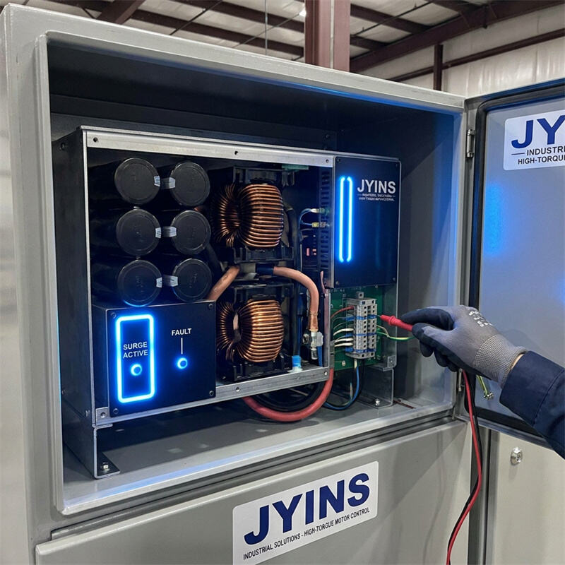
The Core Problem of High-Torque Motor Startups
In B2B industrial systems, off-grid workshops, and marine installations, engineers frequently encounter a persistent issue: high-quality power inverters tripping on overload when attempting to start electric motors. Even when the continuous power rating of the inverter exceeds the nominal rating of the motor by a seemingly safe margin, the startup attempt fails. This failure manifests as a rapid drop in AC voltage, followed by an over-current shutdown on the inverter.
This article delivers a technical analysis of why these failures occur and provides actionable engineering strategies to overcome surge capacity bottlenecks when starting heavy-duty inductive machinery.
Question: Why do standard inverters fail during high-torque motor startups, and how do we resolve surge capacity limitations?
To resolve inverter surge capacity failures with high-torque motors, system integrators must address the mismatch between the motor's transient mechanical startup torque and the inverter's electrical current-limiting protection. This is solved by calculating the motor's actual Locked Rotor Amps, verifying battery C-rate capabilities, minimizing DC cabling impedance, and deploying electronic soft-start technologies or selecting high-surge toroidal inverters like those manufactured by JYINS.
Understanding the Physics of Motor Startups
To understand why an inverter trips, one must look at the electromagnetic behavior of AC induction motors. When an electric motor is at rest, its rotor is stationary, and its internal magnetic fields are unestablished.
At the instant of startup (time zero), the motor represents a state known as Locked Rotor Amps (LRA). In this state, there is no back electromotive force (Back EMF) generated by the spinning rotor to oppose the grid's voltage. Consequently, the motor behaves as a pure inductive short-circuit.
During this transient startup period (which can last from 200 milliseconds to several seconds depending on the load's inertia), the current drawn by the motor spikes to 5 to 8 times its nominal running current. For example, a 1.5 kW (2 HP) industrial vacuum pump running on 230V AC draws approximately 6.5A. However, during startup, its LRA can easily reach 35A to 50A, requiring over 10 kW of apparent power (VA).
Furthermore, high-torque applications (such as deep-well water pumps, refrigeration compressors, crushers, and hydraulic power packs) require high starting torque to overcome static friction and inertia. High torque directly correlates to high current. If the current is restricted, the motor cannot generate enough torque to turn, extending the LRA duration and prolonging the extreme electrical load on the power source.
Why Inverters Trip: The Protection Mechanisms
Unlike utility power grids, which have virtually infinite current capability to ride through startup surges, a power inverter is a static electronic device with strict physical limits on current delivery. To protect itself from catastrophic failure, the inverter monitors several parameters:
- MOSFET Peak Over-Current: The metal-oxide-semiconductor field-effect transistors (MOSFETs) inside the inverter are rated for a specific maximum current. If a motor's LRA exceeds this limit, the inverter's control loop will instantly shut down the gate drivers (within microseconds) to prevent the silicon from melting due to thermal runaway.
- DC-Link Capacitor Depletion: Inverters convert DC power to high-voltage AC. When a massive surge is demanded, the energy stored in the internal DC-link capacitor bank is depleted within milliseconds. If the DC input source (the battery bank) cannot replenish this energy fast enough, the DC-bus voltage drops, triggering an under-voltage fault.
- DC Input Voltage Sag: A startup surge demands hundreds of amperes from the DC battery bank. This huge current flow causes a voltage drop across the internal resistance of the batteries and the DC delivery cables. If the input voltage at the inverter's terminals drops below its Low Voltage Cutoff (typically 10.5V for 12V inverters or 42V for 48V inverters), the inverter shuts down to protect the battery from over-discharge.
Sizing and Sizing Calculations for Inductive Loads
When designing a system, engineers must calculate the peak startup power rather than nominal run power. Here is the step-by-step engineering approach:
- Step 1: Identify the motor's starting characteristics. Look at the motor nameplate for the NEMA design code or direct LRA rating. If not available, use the multiplier of 6x the continuous wattage as a safety standard.
- Step 2: Determine the required continuous rating. The inverter's continuous AC output should be at least 1.5 times the motor's running wattage to accommodate general operating fluctuations and ambient heat.
- Step 3: Match the inverter's surge rating. The inverter's surge capacity (typically rated for 1 second or 5 seconds) must exceed the motor's LRA power. If a 1.5 kW motor has a startup demand of 9 kW for 1.5 seconds, the inverter must be rated to handle at least 9 kW of peak surge for that duration.
- Step 4: Verify the battery bank capability. A 48V battery system supplying 9 kW of surge must deliver over 187A of DC current. Ensure the battery chemistry (such as Lithium Iron Phosphate) is rated for this C-rate, and that the battery management system (BMS) does not trip on over-current.
Troubleshooting and Mitigation Strategies
If you are experiencing inverter tripping during motor startups, apply the following systematic troubleshooting steps:
- 1. Investigate DC Cabling Impedance: Ensure the DC power cables connecting the battery bank to the inverter are as short as possible and have adequate cross-sectional area. High cable resistance causes significant voltage sag under high current. For high-wattage inverters, use 4/0 AWG (95 square mm) pure copper cables and check all lugs for secure connections.
- 2. Deploy Electronic Soft Starters: A soft starter uses solid-state switches (SCRs) to gradually ramp up the voltage supplied to the motor during startup. This extends the startup ramp from milliseconds to a few seconds, lowering the peak inrush current by up to 50% to 60%. This allows a smaller inverter to successfully start a high-torque motor.
- 3. Implement Variable Frequency Drives (VFDs): A VFD is the ultimate solution for variable speed and startup management. It converts incoming AC to DC and then back to AC at a variable frequency and voltage. By maintaining a constant Volts-per-Hertz ratio, a VFD can start a high-torque motor at its nominal running current (1x multiplier) instead of the 6x LRA multiplier, eliminating inverter surge failures entirely.
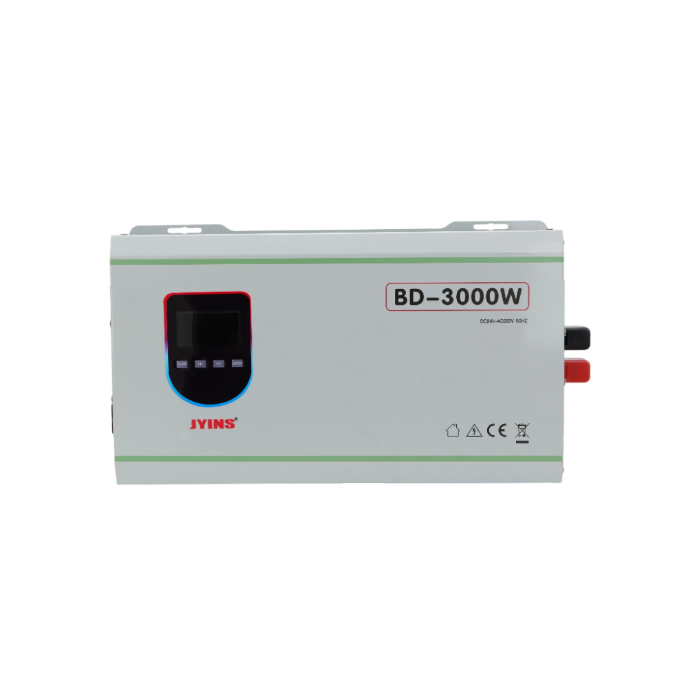
- 4. Select Low-Frequency (Toroidal Transformer) Inverters: Standard high-frequency inverters use electronic switching to step up voltage and have very limited surge capacity (usually only 1.2x to 1.5x continuous rating). Low-frequency inverters, like the JYINS Heavy-Duty series, utilize massive, oversized toroidal copper transformers. These magnetic cores can store electromagnetic energy and handle physical surges of 3 times the continuous rating for up to 10 or 30 seconds. This passive thermal and magnetic buffer is highly resilient against the harsh inductive spikes of motor startups.
Conclusion
Resolving inverter surge failures with high-torque industrial motors is a matter of matching electrical capabilities with mechanical realities. By understanding that induction motors demand extreme startup currents (LRA), engineers can correctly size their equipment, minimize system voltage drops through high-gauge DC wiring, and employ electronic soft-starters or VFDs. For the most demanding B2B industrial environments, choosing low-frequency inverters with toroidal transformers, such as the robust units built by JYINS, provides the necessary safety margin and hardware durability to keep machinery running smoothly.
Table of Contents
- The Core Problem of High-Torque Motor Startups
- Question: Why do standard inverters fail during high-torque motor startups, and how do we resolve surge capacity limitations?
- Understanding the Physics of Motor Startups
- Why Inverters Trip: The Protection Mechanisms
- Sizing and Sizing Calculations for Inductive Loads
- Troubleshooting and Mitigation Strategies
- Conclusion