EN
EN


Understanding Rapid Shutdown (RSD) Systems in Commercial Solar
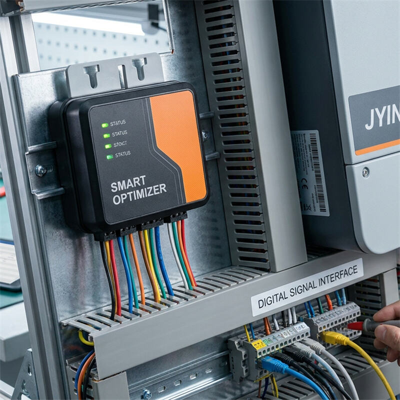
Rapid Shutdown (RSD) is a critical safety requirement for B2B commercial rooftop solar systems, designed to protect firefighters and maintenance personnel from high-voltage hazards. Standards such as NEC 2017/2020 Article 690.12 require that the DC voltage within a solar array be reduced to safe levels (typically under 30 volts) inside the array boundary within 30 seconds of system initiation. To achieve this, modern commercial arrays utilize module-level power electronics (MLPE), such as optimizers or shutdown receivers, that communicate with the central inverter. When a rapid shutdown is initiated, or if communication is lost, these MLPE devices default to an open state, isolating each panel and dropping the system voltage to safe levels. However, if the communication link between the inverter and these devices fails, the system cannot function properly, leading to startup errors, reduced power output, or complete system lockout.
Root Causes of RSD Communication Failure: PLC vs Wireless
Most modern commercial solar systems use one of two primary methods for rapid shutdown communication: Power Line Communication (PLC) or wireless radio-frequency (RF) signals. Each technology has unique vulnerabilities that can lead to communication dropouts:
- Power Line Communication (PLC): This technology transmits high-frequency communication signals directly through the existing DC power lines. While highly convenient because it requires no extra wiring, PLC is highly susceptible to electromagnetic interference (EMI). The high-frequency switching circuits inside modern solar inverters can generate harmonic noise that 'drowns out' the PLC signal. Additionally, poor cable quality, loose connections, or excessive string lengths can cause significant signal attenuation, preventing the optimizer receivers from hearing the shutdown signal from the inverter.
- Wireless Communication: RF-based RSD systems use low-power radio transmitters and receivers. The main root causes of wireless failure include physical obstructions (such as metal roof structures, concrete barriers, or the solar panels themselves), distance limitations, and radio frequency interference from other commercial wireless networks or on-site equipment.
For systems engineers, diagnosing the communication medium is the first step in resolving persistent RSD errors.
Step-by-Step Troubleshooting Protocol for Systems Engineers
When a JYINS inverter displays an 'RSD Communication Fault' or a similar MLPE connection error, systems engineers should follow a systematic troubleshooting process to isolate the root cause:
- Step 1: Verify System Voltages. Measure the open-circuit voltage (Voc) of the individual strings at the combiner box or inverter inputs. If the RSD devices are active and operating correctly, you should read a safe voltage (often around 1 volt per module, depending on the manufacturer). If you read 0 volts or full system Voc, the MLPE devices are either unpowered, damaged, or completely out of sync with the controller.
- Step 2: Check DC Connections and Cable Integrity. Corroded, loose, or wet connectors are a primary source of PLC signal loss. Inspect the crimps on all MC4 connectors and ensure they are dry. Water ingress into a single connector can create a high-resistance path that severely degrades high-frequency communication signal transmission.
- Step 3: Analyze the Inverter PLC Transmitter. Ensure that the PLC signal transmitter integrated into the JYINS inverter is active and receiving power. Check the diagnostic menus on the inverter or via the monitoring application to verify if the transmitter is sending the 'heartbeat' signal.
- Step 4: Perform a String-by-String Scan. In large commercial arrays, disconnect all strings except one, and check if communication is established. Reconnect the strings one by one. This process of elimination allows engineers to identify if a specific string is introducing heavy noise or contains a faulty MLPE receiver that is disrupting the entire communication bus.
Mitigating Electromagnetic Interference (EMI) in Large B2B PV Arrays
In large B2B applications, electromagnetic interference is the most common cause of intermittent PLC communication failures. Inverters are high-power switching devices, and without proper design, they can inject high-frequency noise back into the DC loops, scrambling the delicate PLC heartbeat signal. To combat this, several engineering controls should be implemented:
- Use High-Quality Shielded Cables: Running DC cables in grounded metallic conduits provides excellent shielding against ambient electromagnetic noise. It also prevents the DC cables from acting as antennas that broadcast or absorb stray RF noise.
- Install Magnetic Core Filters: Toroidal magnetic cores (ferrite beads) can be clamped around the DC cables near the inverter inputs. These cores act as low-pass filters, absorbing the high-frequency switching noise from the inverter while allowing the lower-frequency PLC communication signals to pass through unimpeded.
- Correct Cable Routing: Avoid routing DC PV cables parallel to high-voltage AC cables, especially those feeding high-power machinery or variable frequency drives. If AC and DC cables must cross, ensure they do so at a 90-degree angle to minimize inductive coupling.
Hardware Diagnostics: Testing Transmitters, Receivers, and Cables
If systematic troubleshooting points to a hardware failure, physical diagnostic tools must be used. Engineers should utilize a high-quality oscilloscope or a dedicated PLC signal analyzer to probe the DC lines. When checking the lines, look for the following signal characteristics:
- Signal Amplitude: The peak-to-peak voltage of the PLC signal should meet the MLPE manufacturer's minimum specifications (typically a few hundred millivolts). If the signal amplitude is too low, check for excessive string lengths or high-resistance joints.
- Noise Floor: Check the background noise level when the inverter is actively generating power. If the noise floor is close to or higher than the communication signal amplitude, the system is suffering from severe EMI. Clamping additional ferrite filters or adjusting the inverter switching frequency through the JYINS engineering portal can resolve this issue.
- MLPE Receiver Health: Individually test suspect MLPE units with a hand-held programming tool. If a receiver does not respond to a direct RF or PLC command, the unit is damaged and must be replaced.
JYINS Reliable RSD Solutions and Best Integration Practices
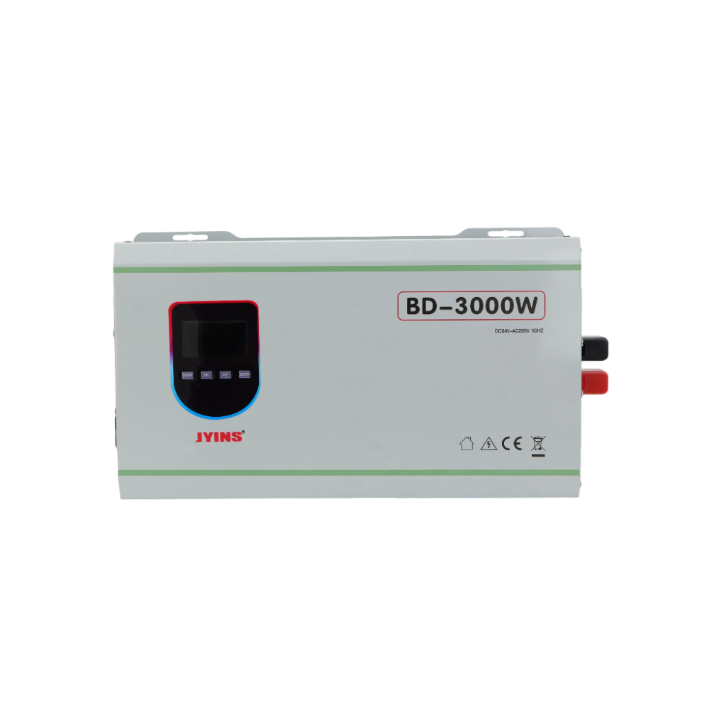
JYINS is dedicated to manufacturing power conversion equipment that integrates seamlessly with industry-leading rapid shutdown systems. Our inverters feature built-in, highly resilient PLC transmitters that are engineered to withstand the demanding electrical environments of commercial rooftops.
Our advanced firmware includes adaptive frequency modulation for PLC signals, allowing the transmitter to shift its communication frequency slightly if it detects heavy harmonic interference in a specific band. This dynamic frequency hopping drastically reduces communication dropout rates in high-noise industrial zones.
Additionally, the JYINS B2B engineering team provides comprehensive system integration support. We help our partners design optimal cable layouts, select the correct magnetic core filters, and configure inverter settings to ensure robust, hassle-free RSD communication. By choosing JYINS, commercial solar integrators ensure their systems remain fully compliant with regional safety standards while maximizing daily energy harvest through stable, uninterrupted communication.
Table of Contents
- Understanding Rapid Shutdown (RSD) Systems in Commercial Solar
- Root Causes of RSD Communication Failure: PLC vs Wireless
- Step-by-Step Troubleshooting Protocol for Systems Engineers
- Mitigating Electromagnetic Interference (EMI) in Large B2B PV Arrays
- Hardware Diagnostics: Testing Transmitters, Receivers, and Cables
- JYINS Reliable RSD Solutions and Best Integration Practices