EN
EN


Structural Challenges of Solar Installations in Seismic Zones
Commercial solar and energy storage installations located in active seismic zones face severe mechanical challenges during earthquakes. When ground movement occurs, buildings and ground-mounted structures sway violently, transferring rapid accelerations and mechanical forces to all attached electrical equipment. For safety officers and structural engineers, selecting inverters for these seismic risk areas requires evaluating more than just electrical specifications. An inverter that is not engineered to withstand seismic forces can break free from its mountings, leading to massive property damage, fire hazards from torn high-voltage cabling, and long-term business interruption. Ensuring the physical and mechanical survivability of these critical power assets is a key element of resilient commercial power system design.
Evaluating Mechanical Anchorage: Structural Calculations and Mounting Systems
The first line of defense for an inverter in a seismic zone is its physical connection to the building structure or ground foundation. If the anchorage fails, internal engineering becomes irrelevant. Systems engineers must evaluate several factors when designing the mounting system:
- Seismic Acceleration Factors (g-force): Engineers must calculate the expected spectral acceleration at the specific installation height. An inverter mounted on a rooftop will experience significantly higher forces than one mounted on a ground-level concrete pad, as the building acts as an amplifier for ground movement. Enclosures must be rated to withstand these multi-axis g-forces (typically ranging from 1.0g to 2.5g in active seismic regions).
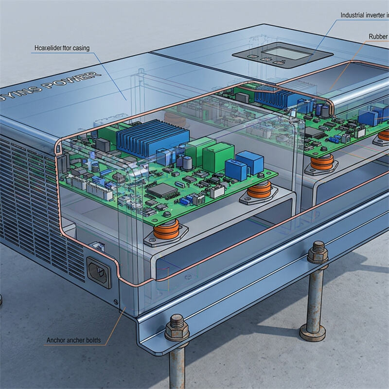
- Anchor Bolt Calculations: The mounting brackets and fasteners must be sized using precise structural calculations. This involves determining the shear and tension forces that the fasteners will experience during an earthquake. High-strength steel anchor bolts (such as grade 8.8 or stainless steel) must be used, and they should be secured into concrete structures using approved chemical or mechanical anchors.
- Structural Enclosure Integrity: The inverter enclosure itself must have sufficient structural rigidity. Thin sheet metal cabinets can buckle under high dynamic loads, causing the internal mounting points to tear. Heavy-duty steel or reinforced aluminum enclosures with internal bracing are necessary to maintain cabinet shape and protect internal components.
Protecting the Heart of the Inverter: Internal PCB Vibration Dampening
While external anchorage keeps the inverter on the wall, the internal electronics must survive the violent vibrations and shocks. Inside a modern commercial inverter, the most sensitive components are the printed circuit boards (PCBs) and high-density power modules (such as IGBTs).
An earthquake creates high-frequency vibrations that propagate through the inverter cabinet. If these vibrations reach the PCBs, they can cause the circuit boards to flex. This flexing places immense stress on solder joints, leading to micro-cracks that sever electrical connections. Additionally, heavy components mounted on the PCB (such as large capacitors, inductors, and heat sinks) can act as pendulums, ripping themselves off the board under high g-forces.
To prevent internal failures, JYINS engineers utilize advanced shock-resistance design standards for our seismic-rated inverters:
- Dampened Mounting Standoffs: Instead of screwing PCBs directly to the rigid metal chassis, JYINS uses specialized elastomeric or rubberized standoffs. These mounts absorb high-frequency vibrations and shock energy, drastically reducing the dynamic acceleration transferred to the delicate electronics.
- Underfilling and Structural Adhesives: For heavy electronic components, JYINS applies structural adhesives and underfill resins. This process mechanically bonds the components to the PCB surface over a larger area, distributing the shock forces and protecting the individual solder connections.
- Conformal Gel Coatings: In addition to moisture protection, the thick silicone-based conformal gel coatings used on JYINS circuit boards provide damping characteristics, helping to absorb mechanical energy and prevent component resonance during shaking.
Case Studies and Shake Table Testing Standards for Power Electronics
How do B2B buyers know if an inverter will actually survive an earthquake? The only reliable verification is physical testing conducted on a multi-axis shake table. During these tests, the inverter is mounted to the table and subjected to simulated earthquake accelerations that match or exceed real-world historical seismic profiles.
- ICC-ES AC156 Compliance: This is the premier international standard for the seismic qualification of non-structural components. To achieve AC156 certification, the inverter must remain physically intact and operational after being subjected to rigorous multi-axis shake tests.
- IEEE 693: This standard applies to electrical equipment used in substations, setting strict seismic design and testing criteria. Inverters designed for utility-scale solar projects in seismic zones must meet these high-strength standards.
JYINS has invested heavily in physical testing for our heavy-duty inverter lineup. Our seismic-rated models are fully certified under ICC-ES AC156 and IEEE 693. During testing, our inverters continued to operate flawlessly even when subjected to horizontal and vertical forces exceeding 2.0g, proving the effectiveness of our physical design and component dampening systems.
Environmental Hazards Post-Earthquake: Dust, Water, and Cable Stress
When evaluating seismic-zone installations, engineers must also consider the environmental conditions immediately following an earthquake. Earthquakes often cause structural damage that leads to secondary hazards, such as broken water pipes, collapsing ceilings that release thick dust, and heavy structural shifting that places physical stress on electrical cabling.
- Cable Stress Relief: To prevent shifting structures from tearing cables from the inverter, engineers should design the cable entries with flexible conduit loops. These loops provide physical slack, allowing the inverter and the conduit to move independently without placing tension on the electrical terminals.
- Ingress Protection (IP Rating): Following an earthquake, dusty and wet conditions are common. JYINS seismic-rated inverters feature IP66-rated enclosures with high-performance synthetic rubber gaskets. These gaskets remain sealed even after the cabinet has experienced mechanical distortion, preventing water and dust ingress from causing secondary electrical failures.
JYINS Earthquake-Resilient Engineering: Built to Endure
JYINS is dedicated to manufacturing power conversion equipment that B2B operators can rely on in the most challenging situations. Our seismic-rated inverters are engineered from the ground up for maximum physical and electrical resilience.
By integrating JYINS inverters with robust mechanical anchorage and advanced internal PCB shock-resistance into your project, you are choosing a system designed to endure the worst natural disasters. Our engineering team works closely with B2B structural and electrical engineers to provide comprehensive mounting layout drawings, anchor bolt specifications, and seismic certification documentation, ensuring a safe, secure, and compliant power installation that will stand strong when it matters most.
Table of Contents
- Structural Challenges of Solar Installations in Seismic Zones
- Evaluating Mechanical Anchorage: Structural Calculations and Mounting Systems
- Protecting the Heart of the Inverter: Internal PCB Vibration Dampening
- Case Studies and Shake Table Testing Standards for Power Electronics
- Environmental Hazards Post-Earthquake: Dust, Water, and Cable Stress
- JYINS Earthquake-Resilient Engineering: Built to Endure