EN
EN


The Crucial Role of Short-Circuit Withstand Ratings in Industrial Power
Heavy-duty industrial power stations, such as those powering mining operations, chemical plants, and massive manufacturing facilities, operate within high-energy electrical grids. In these settings, electrical safety is of paramount importance. When an electrical fault occurs, such as a short circuit down the line from a major distribution busbar, the amount of energy released is immense. A short-circuit event can deliver currents that are tens or hundreds of times larger than the normal operating current of the facility. This massive surge of current places extreme physical and thermal stress on all components in the electrical path, including switchgear, circuit breakers, busbars, and inverters. To prevent catastrophic hardware destruction, explosions, and injury to personnel, systems engineers must carefully evaluate and specify the Short-Circuit Withstand (Icw) rating of all electrical infrastructure.
Defining Icw: Mechanical, Thermal, and Electrical Stress Limits
The Short-Circuit Withstand Current (Icw) is a standardized metric defined by international engineering bodies, such as the International Electrotechnical Commission (IEC 61439). The Icw rating specifies the maximum r.m.s. (root-mean-square) value of short-circuit current that a component or assembly can safely withstand for a designated period of time (typically 1.0 second, though sometimes rated for 0.5 or 3.0 seconds) without sustaining permanent damage or compromising safety. To evaluate Icw, engineers must understand the two distinct stresses that short circuits impose on electrical systems:
- Thermal Stress: The massive current flow generates heat at an exponential rate, proportional to the square of the current (I squared t). Within milliseconds, conductor temperatures can spike to hundreds of degrees Celsius, which can melt insulation, weaken copper mechanical joints, and ruin circuit board substrates.
- Mechanical Stress: Under short-circuit conditions, adjacent conductors carrying these high currents experience immense electromagnetic forces. These forces can bend copper busbars, rip cabling from their mounting brackets, and destroy structural enclosures. The peak force is proportional to the square of the peak current (Ipk), which can be up to 2.2 times the r.m.s. current in AC systems.
An adequate Icw rating ensures that the power station's hardware can survive both the rapid thermal shock and the violent mechanical forces until upstream protective devices (such as high-speed circuit breakers or fuses) can clear the fault.
Calculating Fault Current Capacity and Evaluating System Risks
Evaluating the required Icw rating for an industrial power station is a rigorous mathematical process. Systems engineers must perform a detailed short-circuit study of the entire facility's electrical network. This study involves several key steps:
- Step 1: Determine the Utility Short-Circuit Capacity. Obtain the maximum available short-circuit current (Isc) from the local electrical utility company at the point of common coupling. This represents the starting baseline for the calculations.
- Step 2: Calculate Source Impedance. Model the electrical impedance of all upstream components, including utility lines, substations, high-voltage transformers, and local generators. Lower system impedance results in higher potential short-circuit fault currents.
- Step 3: Account for Local Motor Contribution. In heavy industrial facilities, large electric motors running at the time of a fault can briefly act as generators, feeding additional current back into the short circuit. Engineers must add this motor contribution to the calculated short-circuit current.
- Step 4: Determine the Prospective Fault Current. Calculate the maximum r.m.s. fault current at each critical busbar and power distribution point within the facility. The Icw rating of the switchgear and components installed at these points must exceed these calculated prospective fault currents with an appropriate safety margin (typically 10 to 20 percent).
Selecting Switchgear and Circuit Protection with Appropriate Icw
Once the prospective fault currents are determined, engineers must select components that match or exceed these requirements. When evaluating switchgear and circuit protection devices, keep the following considerations in mind:
- Coordinated Protection (Selectivity): To minimize downtime, the system should be designed with selective coordination. This means that a downstream fault should only trip the circuit breaker directly upstream of that fault, leaving the rest of the facility powered. For this to work, upstream breakers must remain closed during a fault for a short duration, meaning they must have a high Icw rating to withstand the current while waiting for downstream breakers to trip.
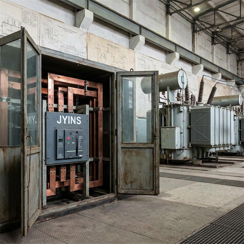
- Integrated Busbar Bracing: In heavy-duty switchgear cabinets, the physical copper busbars must be secured with heavy-duty insulating supports (busbar braces) that are rated to withstand the calculated mechanical forces (Ipk). Ensure that switchgear assemblies have undergone physical type-testing to verify their rated Icw limits.
- Ambient Temperature Derating: High ambient temperatures inside industrial enclosures can reduce the thermal margin of copper conductors. Engineers must apply appropriate derating factors to the Icw ratings if the equipment is operating in hot, unventilated environments.
Integrating JYINS Heavy-Duty Electrical Infrastructure for High-Fault Environments
JYINS is a leading manufacturer of high-reliability power conversion and circuit protection systems designed for demanding B2B applications. Our heavy-duty industrial switchgear, custom circuit breakers, and power distribution units are engineered to meet the highest safety standards in the industry.
JYINS products undergo extensive type-testing in accredited high-power testing laboratories. During these tests, our switchgear assemblies are subjected to simulated short-circuit currents up to 50kA or 100kA for a full second, verifying that our structures, busbars, and insulating mounts can easily survive real-world fault conditions.
Our advanced circuit breakers feature fast magnetic trip mechanisms that clear severe short circuits in less than 10 milliseconds, significantly reducing the total thermal energy (I squared t) let-through. This rapid interruption protects downstream cabling, high-performance inverters, and sensitive control equipment from damage, lowering repair costs and minimizing operational downtime.
Compliance Standards: IEC 61439 and UL 891 Requirements
To ensure global compliance and safety, B2B buyers must specify that all power station components comply with major international standards. The most relevant standards for short-circuit withstand performance include:
- IEC 61439-1/-2: This standard defines the requirements for low-voltage switchgear and controlgear assemblies, establishing the test methods and safety factors for verifying Icw, Ipk, and thermal performance.
- UL 891: This standard covers dead-front switchboards used in North America, specifying the mechanical strength and electrical safety margins required to protect against short circuits.
By integrating JYINS certified switchgear and circuit protection systems into your heavy-duty industrial power stations, safety officers and systems engineers can be confident that their facilities are protected by hardware built to withstand the most demanding electrical faults. Our team of engineering experts is available to assist B2B clients with short-circuit calculations, protection coordination studies, and custom equipment selection to ensure a safe, robust, and highly reliable power system.
Table of Contents
- The Crucial Role of Short-Circuit Withstand Ratings in Industrial Power
- Defining Icw: Mechanical, Thermal, and Electrical Stress Limits
- Calculating Fault Current Capacity and Evaluating System Risks
- Selecting Switchgear and Circuit Protection with Appropriate Icw
- Integrating JYINS Heavy-Duty Electrical Infrastructure for High-Fault Environments
- Compliance Standards: IEC 61439 and UL 891 Requirements