EN
EN


Q: What are the key points to review when selecting an inverter for high-vibration marine transport environments, specifically regarding internal solder joints and component support standards?
A:
Marine transport and shipboard power systems challenge inverters far more than land-based applications. In addition to the well-known issue of salt spray corrosion, continuous high-frequency vibration and intense mechanical shock (especially in rough sea conditions) are the primary causes of internal circuit damage in inverters. In marine environments, conventional consumer-grade inverters suffer fatigue fractures at internal solder joints, and heavy inductors or capacitors can come loose, completely paralyzing the system. As a brand deeply rooted in the industrial-grade power market, JYINS has consolidated a set of hardware quality audit standards for inverters used in high-vibration environments, helping B2B buyers accurately identify truly durable equipment.
1. Auditing Solder Processes: The Core of Fatigue Resistance
In high-vibration environments, the PCB (printed circuit board) undergoes slight deformation. If the soldering process is not up to par, solder joints gradually develop micro-cracks, eventually resulting in open circuits or intermittent connections.
- Through-hole technology (THT) depth: For high-current and heavy components (such as main transformer pins and power terminals), JYINS insists on full through-hole soldering rather than surface-mount technology (SMT). When auditing, check that solder joints are full and smooth, and that the solder completely penetrates the PCB holes to form a solid mechanical lock.
- Toughness of lead-free solder: JYINS selects lead-free solder containing specific trace elements to balance electrical conductivity and mechanical toughness. During production, the reflow soldering temperature profile is strictly controlled to minimize internal stress in solder joints, preventing brittle failure under the combined stress of thermal cycling and vibration.
- Stress relief design at solder joints: Examine the PCB layout to see whether the leads of critical components have an appropriate bend radius to absorb the stress caused by mechanical vibration, rather than letting the solder joints bear the pulling force directly.
2. Auditing Component Support and Reinforcement: Preventing Top-Heavy Failures
Large inductors, large electrolytic capacitors, and transformers are the heaviest components inside an inverter. During wave-induced motion, these components generate enormous inertial forces.
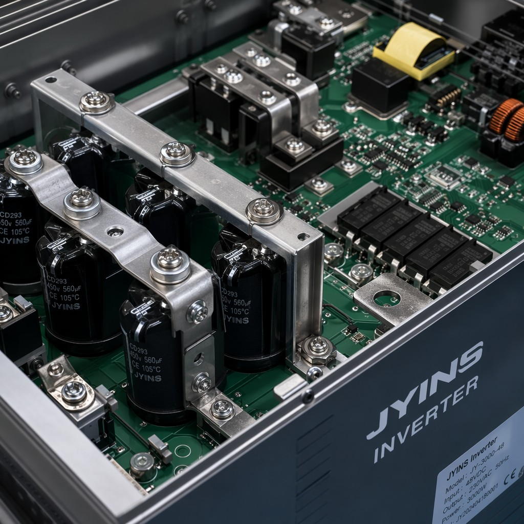
- Three-point support and adhesive bonding: For capacitors taller than 3cm, JYINS uses dedicated mounting brackets or vibration-resistant silicone rubber (RTV adhesive) for secondary reinforcement. This adhesive must have good elasticity and high-temperature resistance, firmly "anchoring" the component to the PCB or chassis base.
- Structural fasteners: Verify whether the transformer is fixed directly to the metal chassis with high-strength bolts rather than being supported solely by the PCB. JYINS industrial-grade inverters typically use a rib-reinforced structure to ensure that the transformer core does not shift even under vibration levels above 2G.
- Cable harnessing: All internal wiring must be tightly bundled with industrial-grade cable ties and secured to dedicated cable ladders. Loose wires rubbing against their insulation under vibration can wear through the insulation or even tear off terminal pins.
3. Mechanical Structure and Enclosure Rigidity
- Modular design: JYINS advocates a modular layout that shortens high-current path routing, reducing the degrees of freedom affected by vibration.
- Shock-resistant enclosure design: The enclosure thickness should meet industrial standards (e.g., aluminum alloy or stainless steel of 1.5mm or more) and be fitted with anti-vibration gaskets. For marine applications, screws must be coated with threadlocker to prevent the enclosure from coming apart under prolonged vibration.
4. Test Verification Standards: Hard Requirements for B2B Buyers
When selecting a JYINS partner, confirm that the product has passed the relevant mechanical reliability tests:
- Vibration test: Compliant with IEC 60068-2-6 or similar marine-grade standards, covering swept-frequency vibration from 10Hz to 150Hz.
- Shock test: Simulates the instantaneous impact forces of loading/unloading and ship berthing (e.g., 15g, 11ms).
5. Business Value: Reducing Offshore Maintenance Costs
Out on the open sea, replacing a failed inverter involves not only expensive spare parts but potentially huge delay costs from helicopter deliveries or unscheduled port calls. Choosing a JYINS inverter that has passed high-vibration audit standards is, in essence, taking out a technical insurance policy on your marine assets. A highly reliable hardware architecture ensures that throughout months of voyaging, the energy system consistently powers communications, navigation, and living facilities.
6. Conclusion
In high-vibration marine transport environments, competition among inverters is not about stacking software features — it is about the solidity of internal hardware craftsmanship. By rigorously auditing solder depth, component support logic, and overall mechanical structure, buyers can effectively filter out low-end products. JYINS treats every internal detail to industrial-grade standards, committed to providing the most solid mechanical reliability for marine energy systems.
Table of Contents
- Q: What are the key points to review when selecting an inverter for high-vibration marine transport environments, specifically regarding internal solder joints and component support standards?
- A:
- 1. Auditing Solder Processes: The Core of Fatigue Resistance
- 2. Auditing Component Support and Reinforcement: Preventing Top-Heavy Failures
- 3. Mechanical Structure and Enclosure Rigidity
- 4. Test Verification Standards: Hard Requirements for B2B Buyers
- 5. Business Value: Reducing Offshore Maintenance Costs
- 6. Conclusion