EN
EN


Introduction to Thermal Stress in Power Electronics
In the world of B2B electrical engineering, heat is the single greatest threat to the reliability, efficiency, and lifespan of power electronics. High-power inverters, which convert DC energy from battery banks or PV arrays to high-voltage AC, are packed with high-speed switching semiconductors, microprocessors, and copper windings. During operation, these components generate significant amounts of waste heat.
To protect their internal circuitry from permanent thermal damage, modern high-power inverters employ a safety feature known as 'Thermal Derating'. When the internal temperature of the inverter exceeds a critical threshold, the device automatically reduces its maximum AC power output. While this prevents hardware destruction, it can cause severe disruption in industrial facilities, leading to unexpected machinery shutdowns or solar production losses.
This article delivers a technical analysis of thermal derating and analyzes the impact of airflow obstruction in electrical cabinets and enclosures.
Question: What is 'Thermal Derating' in high-power inverters, and how does airflow obstruction inside electrical cabinets impact performance?
Thermal derating is a protective control mechanism where an inverter's microprocessor dynamically reduces its maximum AC output power to prevent its internal power semiconductors (such as IGBTs and MOSFETs) from exceeding their safe junction temperatures. Airflow obstruction inside electrical cabinets accelerates this process by preventing heat dissipation, leading to localized heat accumulation, a rapid rise in ambient cabinet temperature, and premature inverter derating. To resolve this, systems integrators must calculate enclosure heat loads, size active exhaust fans, and implement clean airflow pathways using JYINS' advanced thermal management principles.
The Physics of Heat Generation and Semiconductor Junctions
To understand thermal derating, we must look at the heat generation within the inverter's silicon semiconductors. When an inverter is converting power, it experiences internal losses. These losses are primarily composed of conduction losses (due to the internal resistance of the MOSFETs/IGBTs) and switching losses (which occur when the transistors switch on and off thousands of times per second).
These electrical losses are converted directly into heat. This heat raises the temperature of the semiconductor's internal silicon layer, known as the junction temperature (Tj). For industrial-grade silicon semiconductors, the maximum safe junction temperature is typically between 125 degrees Celsius and 150 degrees Celsius.
If the junction temperature exceeds this physical limit, the silicon will undergo thermal runaway, leading to catastrophic physical destruction of the transistor. To prevent this, the inverter's internal sensors continuously monitor the heatsink temperature (Th) and calculate the real-time junction temperature.
When the heatsink temperature crosses a pre-programmed threshold (typically around 45 degrees Celsius to 55 degrees Celsius depending on the model), the inverter's control loop initiates thermal derating. The microprocessor reduces the duty cycle of the switching frequency, which lowers the maximum AC output current. For every degree rise above the threshold, the maximum available power output of the inverter drops linearly (e.g., derating by 2% of rated capacity per degree Celsius).
The Impact of Cabinet Airflow Obstruction
In industrial environments, high-power inverters are almost always installed inside protective metal enclosures or control cabinets to safeguard them from dust, moisture, and unauthorized access. However, enclosing an inverter creates a micro-climate. Without proper thermal design, the cabinet acts as an oven.
Airflow obstruction inside the cabinet is the primary driver of premature thermal derating. Obstruction occurs in several ways:
- Inbalanced Exhaust and Intake Sizing: For hot air to leave a cabinet, cool air must enter. If a cabinet has a high-CFM (Cubic Feet per Minute) exhaust fan but has small or blocked intake vents, the fan will struggle against static pressure, resulting in a dramatic reduction in actual airflow.
- Clogged Dust Filters: Industrial workshops are filled with airborne particles, metallic dust, and lint. Over time, these particles accumulate on the intake cabinet filters. A clogged filter can restrict airflow by up to 80% to 90%, causing the internal cabinet temperature to skyrocket within minutes of high-load inverter operation.
- Poor Component Placement: Heat rises. If the inverter is physically mounted near other heat-generating components (such as battery chargers, line reactors, or power transformers) inside the cabinet, it will ingest pre-heated air, reducing its heatsink's heat dissipation capability. Furthermore, if there is insufficient clearance around the inverter's intake and exhaust vents (typically requiring at least 150 mm of free space), air will recirculate locally, forming hot air pockets.
Calculating Thermal Load and Enclosure CFM Requirements
To prevent thermal derating, systems integrators must calculate the required airflow rate (CFM) to dissipate the heat generated by the inverter. The required formula is:
CFM = ( 3.16 P_loss ) / delta_T
Where:
- P_loss is the heat dissipation rate (waste heat) of all components inside the cabinet, measured in Watts. This is calculated based on the inverter's conversion efficiency. For a 10 kW inverter operating at 93% efficiency, the heat loss is 7% of 10 kW, which equals 700 Watts.
- delta_T is the allowable temperature rise inside the cabinet relative to the external ambient temperature, measured in degrees Fahrenheit (T_inside - T_outside).
For example, if the maximum external ambient temperature is 95 degrees Fahrenheit (35 degrees Celsius), and we want to limit the internal cabinet temperature to 113 degrees Fahrenheit (45 degrees Celsius) to prevent derating, the allowable temperature rise (delta_T) is:
113 - 95 = 18 degrees Fahrenheit.
Using the formula, the required airflow rate is:
CFM = ( 3.16 700 Watts ) / 18 = 122.8 CFM.
To ensure reliable operation under real-world conditions, engineers should select an exhaust fan rated for at least 150 CFM to account for dust filter restriction and static pressure losses.
Engineering Guidelines for Cabinet Thermal Management
To resolve thermal derating issues, systems integrators should implement the following engineering best practices:
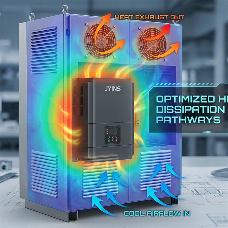
- 1. Maintain Clear Physical Clearance: Install the inverter in the lower, cooler portion of the cabinet. Ensure there is at least 150 mm to 300 mm of clear space around the inverter's built-in cooling fans and vents to prevent local airflow restriction.
- 2. Implement Forced-Air Ventilation: Use high-quality ball-bearing cabinet exhaust fans mounted near the top of the enclosure to pull hot air out, and place louvers/vents at the bottom to draw cool air in. This utilizes natural convection (heat rising) to maximize cooling efficiency.
- 3. Establish a Rigorous Maintenance Schedule: In dusty environments, schedule monthly or quarterly cleanings of all cabinet intake filters. Use washable, high-airflow polyurethane filters and clean them using compressed air.
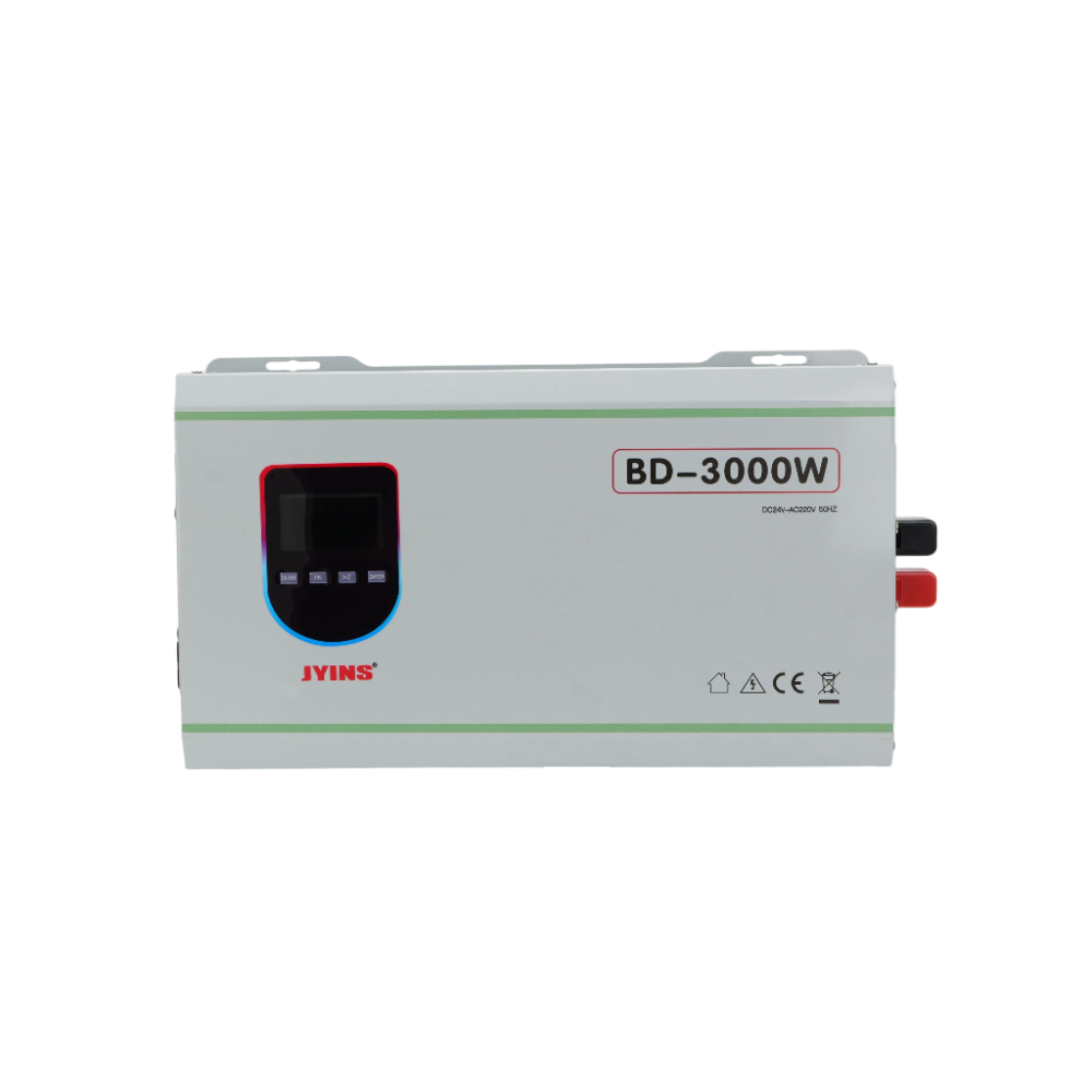
- 4. Select Inverters with Oversized Heat Dissipation: JYINS high-power inverters are engineered for harsh industrial environments. They utilize heavy-duty, oversized aluminum heatsinks with wide fin spacing to prevent dust accumulation. Combined with intelligent, variable-speed brushless DC cooling fans that only run at full speed when Tj rises, JYINS units provide maximum thermal margins, delaying the onset of thermal derating even in confined cabinets.
Conclusion
Thermal derating is an essential safety feature that protects high-power inverters from catastrophic semiconductor failure, but its premature activation due to cabinet airflow obstruction can severely disrupt B2B industrial operations. By understanding the physics of semiconductor heat losses, calculating exact CFM requirements, and implementing optimized forced-air paths, systems integrators can maintain a cool operating environment. Specifying robust JYINS industrial inverters with superior built-in thermal engineering is the final step to ensuring maximum continuous power delivery, even under the most demanding thermal conditions.
Table of Contents
- Introduction to Thermal Stress in Power Electronics
- Question: What is 'Thermal Derating' in high-power inverters, and how does airflow obstruction inside electrical cabinets impact performance?
- The Physics of Heat Generation and Semiconductor Junctions
- The Impact of Cabinet Airflow Obstruction
- Calculating Thermal Load and Enclosure CFM Requirements
- Engineering Guidelines for Cabinet Thermal Management
- Conclusion