EN
EN


Q: How to design a 'Micro-UPS' system for industrial PLC control panels using DC-AC inverters?
Introduction: The Vulnerability of Industrial Automation
In modern manufacturing plants, petrochemical facilities, and municipal water treatment works, Programmable Logic Controllers are the brains of the operation. These solid-state computer systems control complex robotic arms, coordinate conveyor speeds, monitor safety sensors, and regulate chemical flow rates. They operate in real time, executing thousands of lines of logic code per second.
Because PLCs are highly sensitive electronic devices, they require clean, uninterrupted electrical power. Even a minor electrical disturbance, such as a voltage dip lasting only a few milliseconds, can cause a PLC to reboot. When a PLC reboots unexpectedly, the entire production line grinds to a halt. This leads to costly batches of ruined products, damaged tooling, hours of diagnostic downtime, and potential safety hazards.
While large, centralized uninterruptible power supply (UPS) systems are common in factory designs, many facilities require localized, highly robust protection for individual, critical control panels. Designing a localized 'Micro-UPS' system directly inside the PLC control panel using a dedicated DC-AC power inverter offers an efficient, modular, and highly reliable alternative. This engineering guide walks you through the step-by-step process of designing a Micro-UPS system, demonstrating how to integrate JYINS pure sine wave inverters to guarantee continuous automation uptime.
The Anatomy of an Industrial Micro-UPS System
To build a highly reliable Micro-UPS inside an industrial control panel, engineers must integrate four key components into a cohesive system:
- Primary AC-DC Power Supply: Under normal operating conditions, this power supply draws AC grid power and converts it to a stable DC voltage (typically 24V DC) to power the main PLC, sensors, and HMI screens.
- DC Battery Bank and Smart Charger: A localized battery bank (utilizing lithium-iron-phosphate or rugged lead-acid batteries) is wired in parallel to the system. A smart DC charger keeps this battery bank fully charged during normal grid operation.
- DC-AC Pure Sine Wave Inverter: This inverter takes DC power from the backup battery bank and converts it back into stable AC power. This AC output is dedicated to powering any critical AC-powered instruments, solenoid valves, or safety relays within the panel.
- Fast Static Transfer Switch (STS): The STS is the critical switching element. It continuously monitors the main grid AC power. If the grid voltage sags or fails completely, the STS instantly switches the PLC’s AC power source from the grid to the inverter’s AC output.
Step-by-Step Engineering Design and Integration
Designing and building this system requires careful calculations and a strict selection of components:
1. Calculating Load Profile and Inverter Sizing
The first step in the design process is to calculate the total continuous AC load that must be backed up by the Micro-UPS. List every critical AC-powered component inside the panel:
- The main PLC power supply unit (typically 240V or 120V AC input).
- Local HMI display screens.
- Critical sensors and signal transmitters.
- Low-power AC solenoid valves and communication modems.
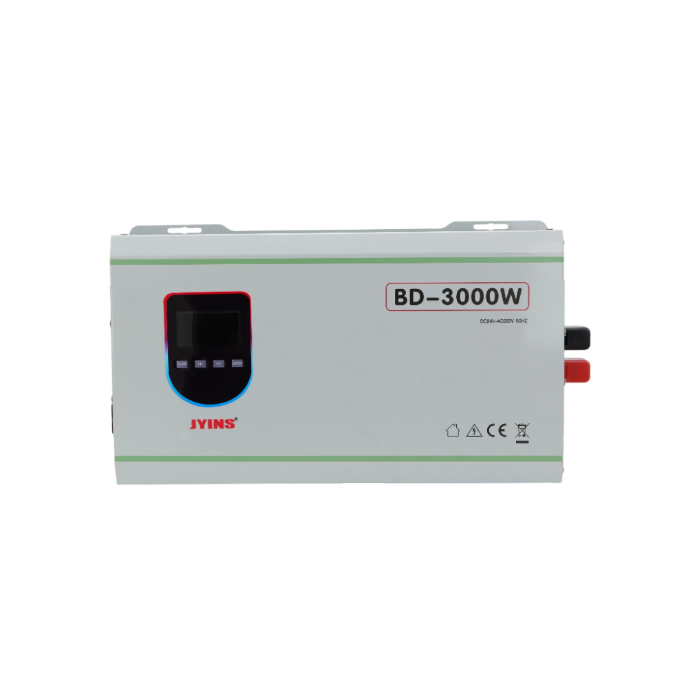
Sum the continuous wattages of these devices and multiply by a safety margin of at least 25 to 30 percent to allow for future panel expansions. For example, if your total critical AC load is 200W, you should select an inverter rated for at least 300W of continuous power. JYINS compact 300W and 500W pure sine wave inverters are ideal for this application, offering a highly reliable power conversion stage in a compact, panel-friendly chassis.
2. Selecting the Inverter: Why Pure Sine Wave is Non-Negotiable
When choosing the DC-AC inverter for a PLC panel, never specify a modified sine wave unit. PLCs, advanced HMI screens, and precise analog input cards contain high-performance switch-mode power supplies. If powered by a modified sine wave inverter, these power supplies will run extremely hot, suffer from capacitor stress, and can inject high-frequency harmonic noise into the PLC's analog input loops. This electrical noise can lead to false sensor readings, erratic valve operations, and permanent hardware damage.
Specify a true pure sine wave inverter, such as the JYINS JYP Series, which delivers a clean, continuous sine wave with less than 3 percent Total Harmonic Distortion. This clean waveform guarantees that your PLC and connected automation accessories operate with the same reliability as if they were running on a utility grid.
3. Minimizing Transfer Time: Meeting the PLC Holdup Time Constraint
Most industrial PLC power supplies are designed to withstand a momentary power loss of up to 10 to 20 milliseconds without rebooting. This interval is known as the 'holdup time.'
Your Micro-UPS design must guarantee that when the grid fails, the transition to inverter power is completed well within this holdup window. A standard mechanical relay is too slow and can suffer from contact bounce, resulting in transition times of 20 to 50ms, which will cause the PLC to reboot.
Instead, engineers must utilize a solid-state Static Transfer Switch based on high-speed thyristors or SCRs. A high-quality STS can detect an AC grid failure and complete the transfer to the active JYINS pure sine wave inverter in less than 5 to 8 milliseconds. This seamless transition is fast enough to ensure the PLC continues executing its logic without interruption.
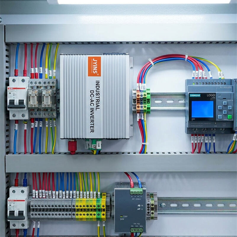
4. Wiring, Layout, and DIN-Rail Mounting Best Practices
When physically mounting the Micro-UPS components inside the PLC control panel, adhere to these industrial wiring and layout standards:
- Thermal Management: Power supplies, chargers, and inverters generate heat during operation. Mount the JYINS inverter in the upper portion of the control panel, leaving at least 5 to 10 centimeters of free space around its ventilation slots to allow for natural convection cooling, or integrate active cabinet cooling fans.
- Separate DC and AC Wiring: Keep the high-voltage AC input/output wiring physically separated from low-voltage 24V DC control lines and analog signal cables. Use distinct wire ducts and color-coded wires (e.g., red for DC, black/blue for AC) to prevent electromagnetic interference from bleeding into sensor lines.
- Secure Grounding: Ensure the inverter's chassis ground terminal is securely bonded to the panel's main copper ground bar. The battery bank, charger, and PLC must all share this common, low-impedance ground reference to ensure safety and prevent electrical noise loops.
Conclusion: Bulletproofing Automation with JYINS Power
In the high-stakes world of industrial automation, a localized Micro-UPS is a cost-effective, high-yield insurance policy. By protecting individual, critical PLC panels from the unpredictability of grid power sags and blackouts, you eliminate localized production interruptions and safeguard expensive automation hardware.
By integrating JYINS high-performance, pure sine wave DC-AC inverters into your Micro-UPS designs, panel builders and industrial automation engineers guarantee clean, stable, and resilient power. JYINS inverters provide the precise wave control, high energy efficiency, and compact, rugged build quality required to thrive in harsh industrial cabinets. Secure your factory’s brains by choosing JYINS to power your control systems.
Table of Contents
- Introduction: The Vulnerability of Industrial Automation
- The Anatomy of an Industrial Micro-UPS System
- Step-by-Step Engineering Design and Integration
- 1. Calculating Load Profile and Inverter Sizing
- 2. Selecting the Inverter: Why Pure Sine Wave is Non-Negotiable
- 3. Minimizing Transfer Time: Meeting the PLC Holdup Time Constraint
- 4. Wiring, Layout, and DIN-Rail Mounting Best Practices
- Conclusion: Bulletproofing Automation with JYINS Power