EN
EN


Introduction: The Capital Risk of High-Volume OEM Procurement
For B2B procurement directors, electrical wholesalers, and solar system developers, placing a high-volume OEM (Original Equipment Manufacturer) order for power inverters represents a significant financial and operational commitment. A single order can involve thousands of units, destined for critical projects or distributed to global retail networks. In this high-stakes scenario, relying solely on a manufacturer's standard specification sheet or a basic functional test is a dangerous gamble.
If the sourced inverters suffer from underlying design flaws, poor component selection, or sub-optimal thermal engineering, these issues will only manifest once the units are deployed in the field under real-world stress. The cost of a mass field recall, warranty claims, lost client trust, and legal disputes can easily dwarf any initial savings from choosing a low-cost supplier. To mitigate these risks, procurement teams must implement a structured, rigorous sample validation protocol. This article outlines the essential phases of a comprehensive inverter stress-test program that must be conducted on sample units before finalizing high-volume OEM agreements.
Question: How can B2B procurement directors and quality engineers design and conduct a rigorous stress-test protocol on sample inverters to ensure quality before placing large-scale OEM orders?
To answer this question, quality control teams must perform three distinct phases of stress testing: electrical stress testing, thermal and environmental testing, and protection system verification.
Phase One: Electrical Stress Testing
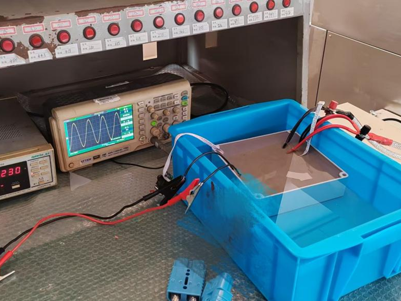
The first step is to verify the electrical robustness of the inverter under continuous and transient load conditions. This phase simulates the severe electrical fluctuations the hardware will experience in industrial power grids or remote battery systems:
- Continuous Full-Load Burn-In Test: The sample inverter should be operated at one hundred percent of its rated nominal capacity continuously for forty-eight to seventy-two hours. This test is designed to force early infantile failures in electronic components, such as semiconductor junctions, transformers, and capacitors. The testing must be conducted at a controlled, warm ambient temperature of forty degrees Celsius to simulate realistic field conditions.
- Overload and Peak Surge Verification: Most industrial equipment (such as pumps, compressors, and power tools) draws a high surge current when starting up, often two to three times its running current. The sample inverter must be subjected to repeated surge tests. Apply a load equal to two hundred percent of the inverter's nominal capacity for its rated surge duration (typically several seconds), repeating this cycle at least fifty times. The inverter must handle these surges without tripping, blowing internal fuses, or suffering semiconductor degradation.
- DC Input Range and Fluctuation Testing: Power inverters operate on variable DC inputs, such as fluctuating battery voltages or solar array outputs. The testing team should vary the input DC voltage between the absolute lowest and highest limits specified by the manufacturer. The inverter must shut down safely at the designated low-voltage cutoff to protect the batteries and shut down at the high-voltage limit to protect its own internal circuitry, recovering automatically once the input voltage returns to nominal ranges.
Phase Two: Thermal and Environmental Stress Testing
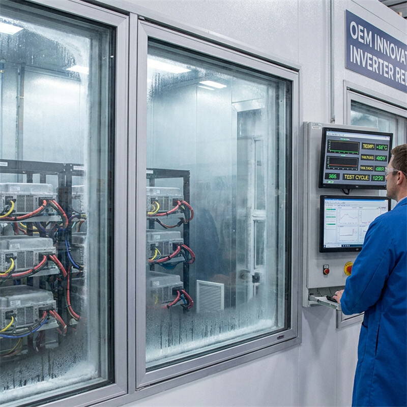
Industrial power inverters are frequently exposed to harsh outdoor climates, high humidity, dust, and vibrations. Environmental chamber testing is critical to verify the physical durability of the inverter housing and internal PCBs:
- High-Temperature Operating Test: Elevate the ambient temperature inside the environmental chamber to fifty degrees Celsius and operate the inverter at full load. This test verifies the efficiency of the inverter's thermal management system (heatsinks and fans) and checks whether the unit undergoes severe thermal de-rating or early thermal shutdown.
- Thermal Shock and Temperature Cycling: Place the non-operating inverter in a temperature chamber and cycle the temperature rapidly between minus twenty degrees Celsius and positive sixty degrees Celsius, holding at each extreme for two hours. This rapid thermal expansion and contraction puts immense physical stress on solder joints, internal component leads, and mechanical seals. After completing fifty cycles, verify that the inverter still functions perfectly and that no micro-cracking has occurred on the PCB solder joints.
- High-Humidity and Insulation Resistance Testing: Subject the inverter to an environment with ninety-five percent non-condensing relative humidity at forty degrees Celsius for forty-eight hours. Afterward, immediately perform a dielectric strength (Hi-Pot) and insulation resistance test to ensure that moisture has not penetrated the protective conformal coating of the internal electronics, which would present a high risk of short circuits or electric shock.
Phase Three: Protections and Failure-Mode Testing
A high-quality inverter must not only perform well under normal conditions; it must also fail-safe under extreme fault conditions without presenting a hazard to the user or surrounding equipment:
- Output Short-Circuit Protection: While the inverter is operating at full load, create a direct short circuit across the AC output terminals. A well-designed inverter must detect the short circuit and shut down its output stages within microseconds. Repeat this test twenty times. The inverter must survive every short-circuit event and resume normal operations immediately once the short circuit is removed.
- Reverse Polarity Verification: Connect the DC input cables in reverse (positive to negative and negative to positive). While some low-cost inverters will be destroyed by this mistake, industrial-grade units should feature integrated reverse polarity protection (such as internal protective diodes or mosfet switches) that prevents any damage, requiring only the replacement of a fuse or resetting of a switch.
- Electrostatic Discharge (ESD) and EMI Immunity: Apply standard static electricity discharges (according to IEC 61000-4-2) to the inverter chassis and control buttons to ensure that user touch does not disrupt the inverter's operations or damage its internal microcontrollers.
Sourcing with Confidence: The JYINS Commitment
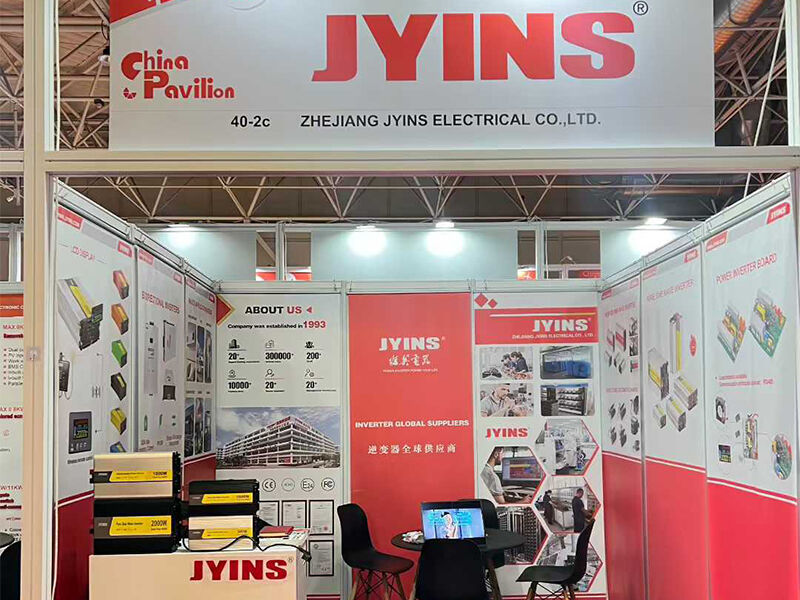
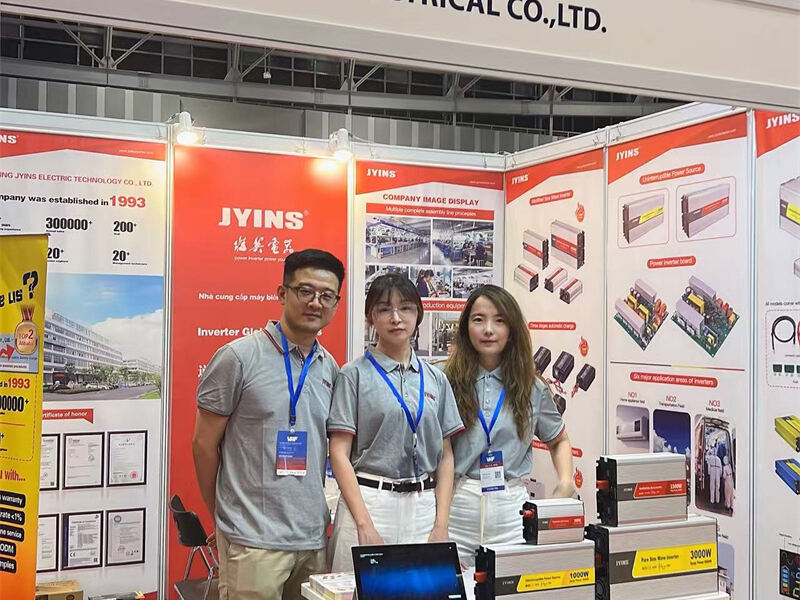
At JYINS Electrical, we do not fear customer stress testing; we welcome it. We maintain our own state-of-the-art testing facility where we subject every new design and OEM sample to the exact rigorous testing standards outlined above. When you partner with JYINS for your OEM or ODM projects, we provide complete, transparent test reports, thermal imaging data, and bills of materials. This level of transparency gives B2B procurement managers the absolute confidence that the customized inverters they receive are engineered to withstand the harshest field conditions and deliver exceptional reliability.
Conclusion: Secure Your Supply Chain Through Rigorous Testing
Conducting a systematic, three-phase stress test on sample inverters is the ultimate insurance policy for high-volume B2B procurement. By investing the time and resources to rigorously test sample hardware for electrical endurance, environmental resilience, and fault protection, you protect your capital investment, minimize warranty-related operational costs, and guarantee that your brand continues to represent uncompromising quality in the global marketplace.
Table of Contents
- Introduction: The Capital Risk of High-Volume OEM Procurement
- Question: How can B2B procurement directors and quality engineers design and conduct a rigorous stress-test protocol on sample inverters to ensure quality before placing large-scale OEM orders?
- Phase One: Electrical Stress Testing
- Phase Two: Thermal and Environmental Stress Testing
- Phase Three: Protections and Failure-Mode Testing
- Sourcing with Confidence: The JYINS Commitment
- Conclusion: Secure Your Supply Chain Through Rigorous Testing