EN
EN



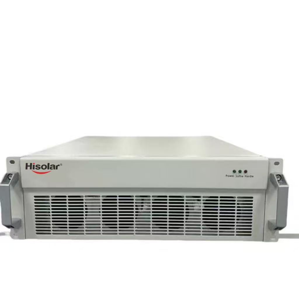


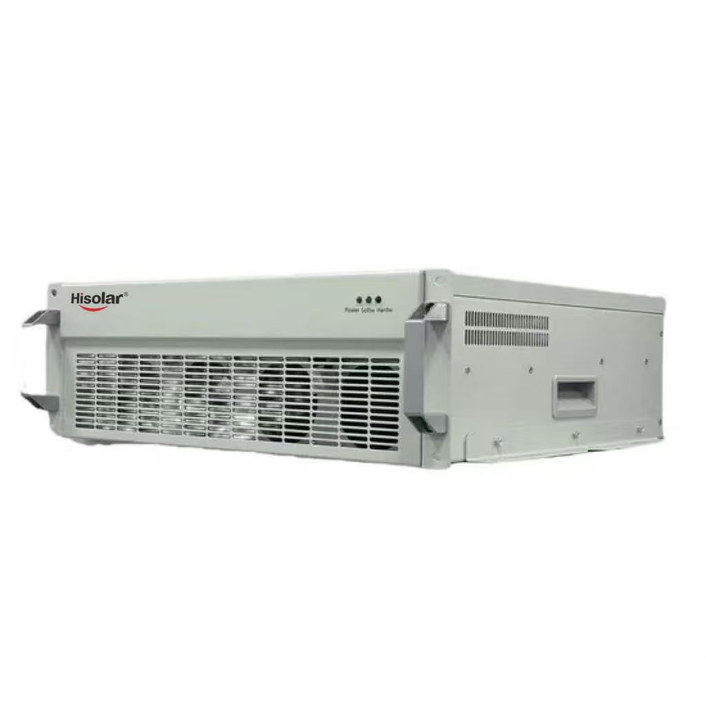
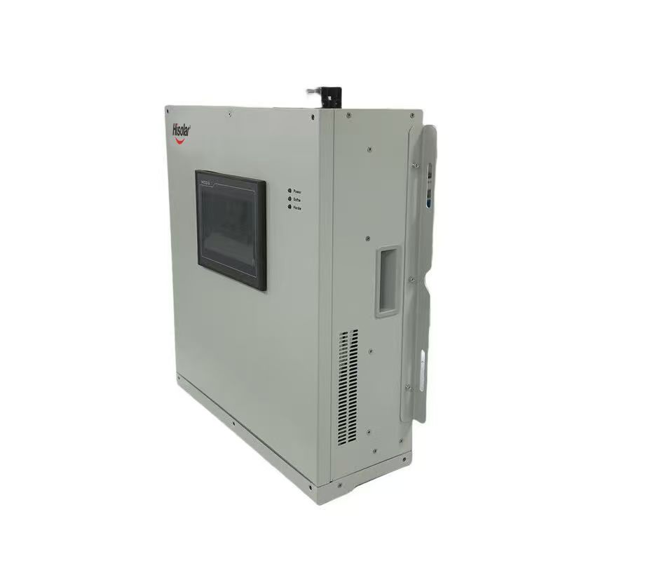
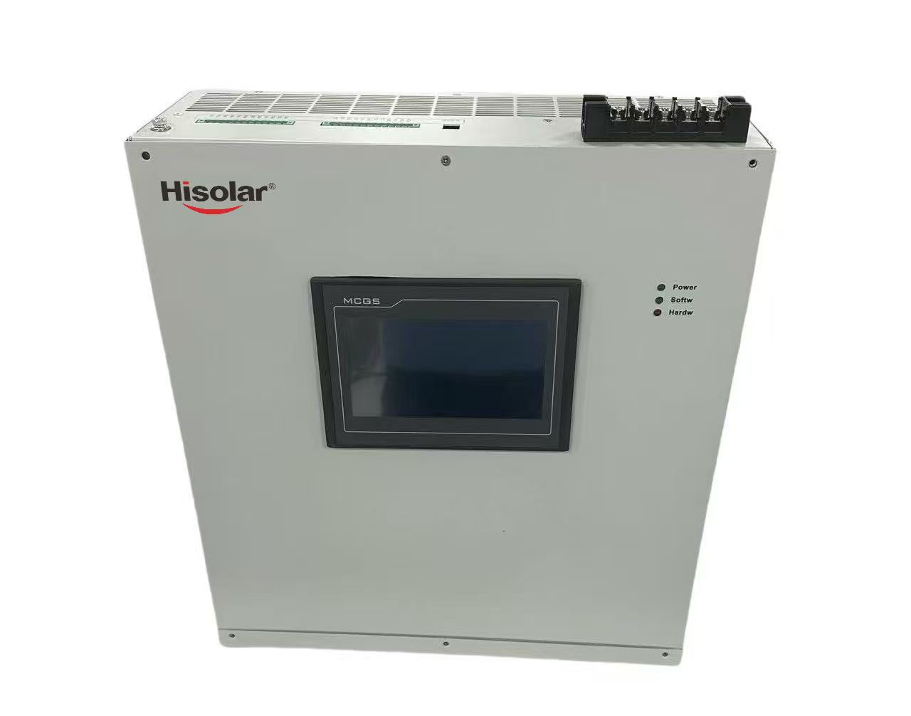
Technical Parameter | ||||
Rated Voltage |
220v |
400v |
480v |
690v |
Rated Capacity |
15/25/50/75/100/200A |
15/25/50/75/100/200A |
15/25/50/75/100/200A |
15/25/50/75/100/200A |
Phase System |
3P3W/3P4W |
|||
Main Frequency |
50/60Hz ± 5% |
|||
Circuit Topology |
Three-level |
|||
Multiple Compensation Modes |
Harmonic, reactive power, three-phase load imbalance compensation |
|||
Filter Range |
2 to 50 odd harmonics (by order or full compensation) |
|||
Harmonic Filtering Rate |
≥98% |
|||
Filtering Performance |
Typically, THDi ≤ 5% at rated loads |
|||
Three-Phase Load Balancing Effect |
≤ 5% to mitigate negative and zero sequence currents |
|||
Neutral Linear Filtering Capability |
3 times the rated filter current (in case of 4-wire equipment) |
|||
Initial Response Time |
≤50us |
|||
Output Current Limit |
Automatic output limitation within 100% of rated capacity |
|||
Control Algorithm |
Intelligent FFT, ADALINE, Fast Fourierand Instantaneous Reactive Power Algorithms |
|||
Controller |
DSP+FPGA |
|||
Protection |
Hardware protection, software protection |
|||
Control Connections |
Electrical Connections |
|||
Human Machine Interface |
4.3" / 7" / 10" Touch TFT LCD HMI |
|||
Noise |
<60db (<45db at low speed operation) |
|||
Installation Method |
Module embedded (rack), wall-mounted, floor-mounted |
|||
Protection Level |
IP30 maximum |
|||
Cooling Method |
Speed controlled intelligent air-cooled PWM fan |
|||
Colour |
RAL 7035 Industrial Grey/Black |
|||
Ambient Temperature |
-20~55℃ |
|||
Relative Humidity |
95% max, no condensation |
|||
Installation Height |
Rated capacity at altitude ≤2000m, appropriate load shedding at altitude >2000m |
|||
Qualification |
CE, IEEE61000, Type test report, ISO9001:2015 |
|||
Conformity Standard |
IEEE 519, ERG5/4 |
|||
Communication Protocol |
Adopts Modbus RTU remote communication protocol and TCP/IP protocol; Two channel RS485 and CAN bus, support mobile APP operation, support Ethernet |
|||
1.Safety Precaution
Only certified electricians with high-voltage operation qualification are allowed to install, wire and debug the SVG device. Cut off all upper-level power supply before construction, and hang warning signs of “No Closing, People Working”.
Strictly comply with local electrical safety codes. High voltage inside the cabinet may cause electric shock, fire or permanent equipment damage if operated improperly.
Do not disassemble the power module, control panel and internal wiring without manufacturer’s authorization. Unauthorized disassembly will void the warranty.
Keep the installation site well ventilated, dry and dust-free. No flammable, explosive or corrosive gas around the equipment.
Confirm that the incoming voltage, rated current, power factor compensation range and system frequency match the SVG nameplate parameters before wiring.
Wear insulated protective tools during the whole installation process. It is forbidden to touch live terminals, copper bars and wiring terminals.
2. Unpacking & Inspection
Take out the SVG cabinet, accessories, wiring terminals, communication cables and user manual from the packing case.
Visually check the cabinet shell for collision deformation, paint peeling, crack or water soaking damage during transportation.
Check all internal power modules, circuit breakers, CT current transformers, cooling fans and touch screen for looseness or breakage.
Verify that the nameplate model, rated voltage, compensation capacity match your order contract.
Check attached accessories: grounding copper wire, communication wire, mounting bolts, CT transformers, installation brackets. If any parts are missing or damaged, contact supplier immediately.
3. Site & Foundation Installation
3.1 Installation Environment Requirements
Ambient temperature: -10℃ ~ +45℃; avoid direct sunlight heating the cabinet.
Relative humidity: ≤90%, no condensation inside cabinet.
Altitude: ≤1000m; derating is required if altitude exceeds 1000m.
Protection class: Indoor cabinet IP20; install in independent power distribution room with dustproof and waterproof measures.
3.2 Foundation Fixing Steps
Reserve flat concrete foundation according to cabinet dimension, keep horizontal levelness error ≤2mm/m.
Hoist the SVG cabinet to the pre-placed foundation, align the mounting holes at cabinet bottom.
Use expansion bolts to fix the cabinet tightly on ground; shake the cabinet slightly to confirm no looseness.
Leave ≥800mm maintenance space on front and rear sides of the cabinet for later overhaul.
Connect cabinet ground terminal to factory general grounding grid with standard grounding copper bar, grounding resistance ≤4Ω.
4. Electrical Wiring Installation
4.1 Main Power Circuit Wiring
Confirm upper power distribution cabinet is fully power-off, lock the isolation switch.
Connect three-phase incoming cables L1/L2/L3 to the AC input terminals on SVG cabinet top in sequence.
Connect SVG output compensation copper bars to the busbar of the load side that needs reactive power compensation.
Tighten all copper bar bolts with torque wrench to avoid poor contact and overheating.
Install thermal shrink tubes on all wiring terminals for insulation protection.
4.2 CT Current Transformer Wiring
Mount CT on the main bus of the compensated load circuit, the primary side of CT passes through the main cable.
Connect CT secondary two-core signal wire to the SVG control cabinet CT sampling terminal, strictly follow wiring mark A+/A-, B+/B-, C+/C-.
Reminder: CT secondary circuit must not open circuit during operation, which will generate dangerous high voltage.
Keep CT signal cable separated from high-power cable to avoid electromagnetic interference.
4.3 Control & Communication Wiring
Connect 24V DC auxiliary power supply wire to the control panel power terminal.
Connect RS485 communication cable to touch screen or remote monitoring host, support Modbus-RTU protocol.
Connect fault alarm signal wire to user’s DCS distribution control system (normally open relay output).
5. Pre-Power-On Inspection
Recheck all three-phase main wiring sequence, confirm no phase short circuit or wrong connection.
Test insulation resistance between live wire and ground with megohmmeter, insulation value ≥10MΩ.
Check CT secondary wiring integrity, ensure no open circuit, loose terminal or reverse polarity.
Confirm cooling fans, internal power modules and touch screen are installed firmly.
Clear all redundant wires, metal scraps and foreign objects inside the cabinet.
Check grounding connection is reliable and meets resistance standard.
6. Power-On Debug Operation
Close the upper isolation switch and SVG internal circuit breaker step by step.
Touch screen lights up, enter main interface, system automatically self-check all hardware modules.
Set system basic parameters on touch screen: grid rated voltage, frequency, CT transformation ratio, target power factor, compensation response speed.
Select operation mode: capacitive reactive power compensation / inductive reactive power compensation / automatic dynamic full compensation.
Switch SVG to run mode, observe real-time power factor, harmonic current and reactive power data on screen.
Monitor cabinet internal fan operation and module temperature; normal working temperature shall not exceed 70℃.
Simulate load fluctuation to verify SVG fast dynamic compensation effect.
7. Daily Maintenance Notes
Cut off power supply completely before any internal maintenance work.
Clean dust on power modules, heat sink and fans every 3 months to avoid heat dissipation blockage.
Regularly check wiring terminal temperature, replace aging cables and loose bolts in time.
If the equipment stops for a long time, power on and run for 30 minutes every month to prevent moisture inside modules.
Do not place any sundries on the top of SVG cabinet, keep air intake and outlet vents unobstructed.
8. Common Troubleshooting
Touch screen no display: Auxiliary control power loss, check 24V DC wiring and circuit breaker.
System over-temperature alarm: Fan damaged, air vent blocked or long-time full-load operation; clean heat sink or replace fan.
CT sampling fault: CT secondary wire open/reversed, recheck signal wiring polarity and tightness.
Over-current protection trip: Three-phase short circuit or overload of power grid; cut off power to inspect external wiring.
Communication failure: RS485 cable loose or wrong address code; re-plug communication wire and match Modbus address.
Hisolar (Zhejiang JYINS Electrical Co., LTD.),specializing in the production of power inverters, hybrid solar inverter, customized inverter PCB boards, and other clean energy solutions.